Reinforcing steel bar shearing device capable of shearing efficiently and milling end face

A technology of shearing device and end face grinding, which is applied in the direction of grinding drive device, positioning device, grinding machine tool parts, etc., which can solve the problems of personnel injury and a large amount of manpower, and achieve the effect of avoiding grinding and milling

Inactive Publication Date: 2020-11-27
温州空云如电子科技有限公司
View PDF0 Cites 1 Cited by
  • Summary
  • Abstract
  • Description
  • Claims
  • Application Information

AI Technical Summary

Problems solved by technology

[0002] Rebar is an indispensable material in construction. The function of shearing is often used in the processing of rebar. The existing rebar shearing device requires a lot of manpower, which is easy to cause damage to personnel. The end face of grinding and milling is prone to other accidents. This device can cut the steel bar with high efficiency, and at the same time can grind and mill the end face of the steel bar to avoid unnecessary damage. The invention describes a steel bar that can be cut and milled at the end face with high efficiency. The shearing device can solve the above problems

Method used


Image

  • Reinforcing steel bar shearing device capable of shearing efficiently and milling end face
  • Reinforcing steel bar shearing device capable of shearing efficiently and milling end face
  • Reinforcing steel bar shearing device capable of shearing efficiently and milling end face

Examples


Embodiment Construction

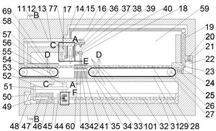
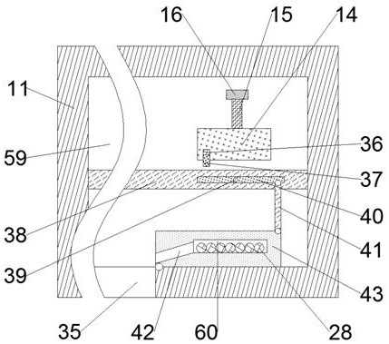
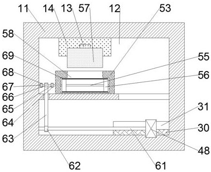
[0017] Combine below Figure 1-Figure 7 The present invention is described in detail, and for convenience of description, the orientations mentioned below are now stipulated as follows: figure 1 The up, down, left, right, front and back directions of the projection relationship itself are consistent.

[0018]A steel bar shearing device capable of high-efficiency shearing and end face grinding according to the present invention includes a shearing body 11, a shearing cavity 59 is opened in the shearing body 11, and a device in which the bottom wall of the shearing cavity 59 is connected. There is a transmission cavity 35, and the right wall of the shearing cavity 59 is connected with an abutting cavity 22, and the abutting and shearing mechanism 101 is arranged in the said shearing cavity 59, and the abutting and shearing mechanism 101 includes a Cut off the guide rail slide seat 77 on the left wall of the chamber 59, the guide rail slide seat 77 is provided with the guide rai...


PUM


Abstract

The invention discloses a reinforcing steel bar shearing device capable of shearing efficiently and milling an end face. The reinforcing steel bar shearing device comprises a shearing body, and a shearing cavity is formed in the shearing body. The reinforcing steel bar shearing device is mainly applied to shearing of the reinforcing steel bars in the industry, and in the shearing process, throughabutting of an abutting block and the to-be-sheared reinforcing steel bars, a to-be-sheared reinforcing steel bar can be cut by a cutting device through an abutting shearing mechanism, and meanwhile,the to-be-sheared reinforcing steel bar can be compressed through an abutting sliding rod to avoid cutting failure, the to-be-sheared reinforcing steel bar can fall into a containing cavity in time through abutting of an ejector block and an abutting lever after being sheared, and then the shearing work can be carried out in order; and meanwhile, the end face of the to-be-ground-and-milled reinforcing steel bar can be effectively ground and milled through a clamping mechanism, excessive grinding and milling of the to-be-ground-and-milled reinforcing steel bar can be avoided through a limitingclamping block, the to-be-ground-and-milled reinforcing steel bar can be clamped, and the clamping mechanism is meshed with a main transmission gear through movement of an auxiliary transmission gear,thereby rotating the clamping mechanism.

Description

technical field [0001] The invention relates to the related field of steel bar shearing, in particular to a steel bar shearing device capable of high-efficiency shearing and end face grinding. Background technique [0002] Rebar is an indispensable material in construction. The function of shearing is often used in the processing of rebar. The existing rebar shearing device requires a lot of manpower, which is easy to cause damage to personnel. The end face of the milling is prone to other accidents. This device can cut the steel bar with high efficiency, and at the same time can grind and mill the end face of the steel bar to avoid unnecessary damage. The invention describes a steel bar that can be cut and milled at the end face with high efficiency. The shearing device can solve the above problems. Contents of the invention [0003] In order to solve the above problems, a steel bar shearing device capable of high-efficiency shearing and end face milling is designed in t...

Claims


Application Information

Patent Timeline
Patent Type & Authority Applications(China)
IPC IPC(8): B21F11/00B21F23/00B23C3/00B23Q3/00B23Q1/25B23Q7/00B24B5/04B24B47/12B24B41/06B24B41/04
CPCB21F11/00B21F23/00B23C3/00B23Q1/25B23Q3/00B23Q7/00B24B5/04B24B41/04B24B41/06B24B47/12
Inventor 黄增军
Owner 温州空云如电子科技有限公司
Why Eureka
Try Eureka