Automatic type lifting door mechanism

A lifting door, automatic technology, applied in the direction of electric processing equipment, metal processing machinery parts, manufacturing tools, etc., can solve the problems of easy twisting of steel wire ropes, inconsistent angle and tension of two strands of steel wire ropes, etc., to reduce the size of the structure, The effect of reducing volume and reducing stroke requirements

Active Publication Date: 2020-11-27
力同机械自动化(上海)有限公司
View PDF8 Cites 1 Cited by
  • Summary
  • Abstract
  • Description
  • Claims
  • Application Information

AI Technical Summary

Problems solved by technology

However, the above structure still has the problem that the two steel wire ropes are easily twisted together, and the angle and tension of the two steel wire ropes may be inconsistent.

Method used


Image

  • Automatic type lifting door mechanism
  • Automatic type lifting door mechanism
  • Automatic type lifting door mechanism

Examples


Embodiment Construction

[0037] In order to further understand the content of the present invention, the present invention will be described in detail in conjunction with the accompanying drawings and specific embodiments.

[0038]In describing the present invention, it is to be understood that the terms "center", "upper", "lower", "front", "rear", "left", "right", "vertical", "horizontal", The orientations or positional relationships indicated by "top", "bottom", "inner", "outer", etc. are based on the orientations or positional relationships shown in the drawings, and are only for the convenience of describing the present invention and simplifying the description, rather than indicating or implying the It should not be construed as limiting the invention that a device or element must have a particular orientation, be constructed, and operate in a particular orientation.

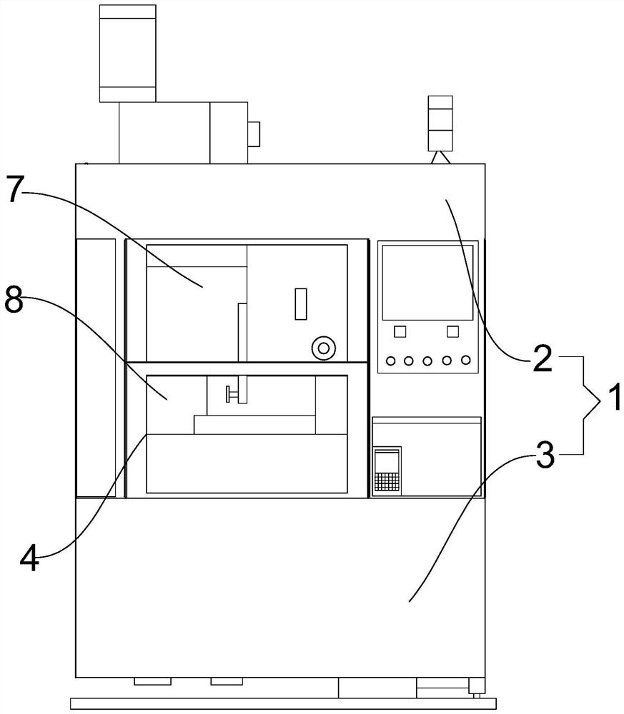
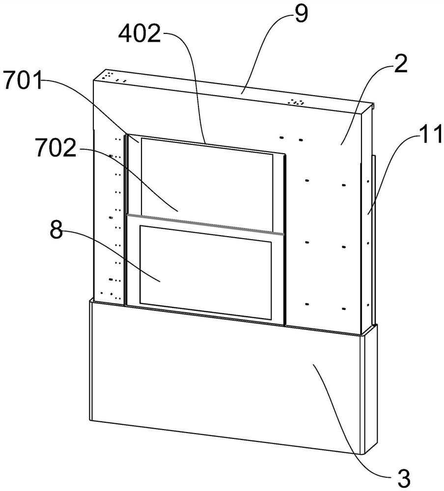
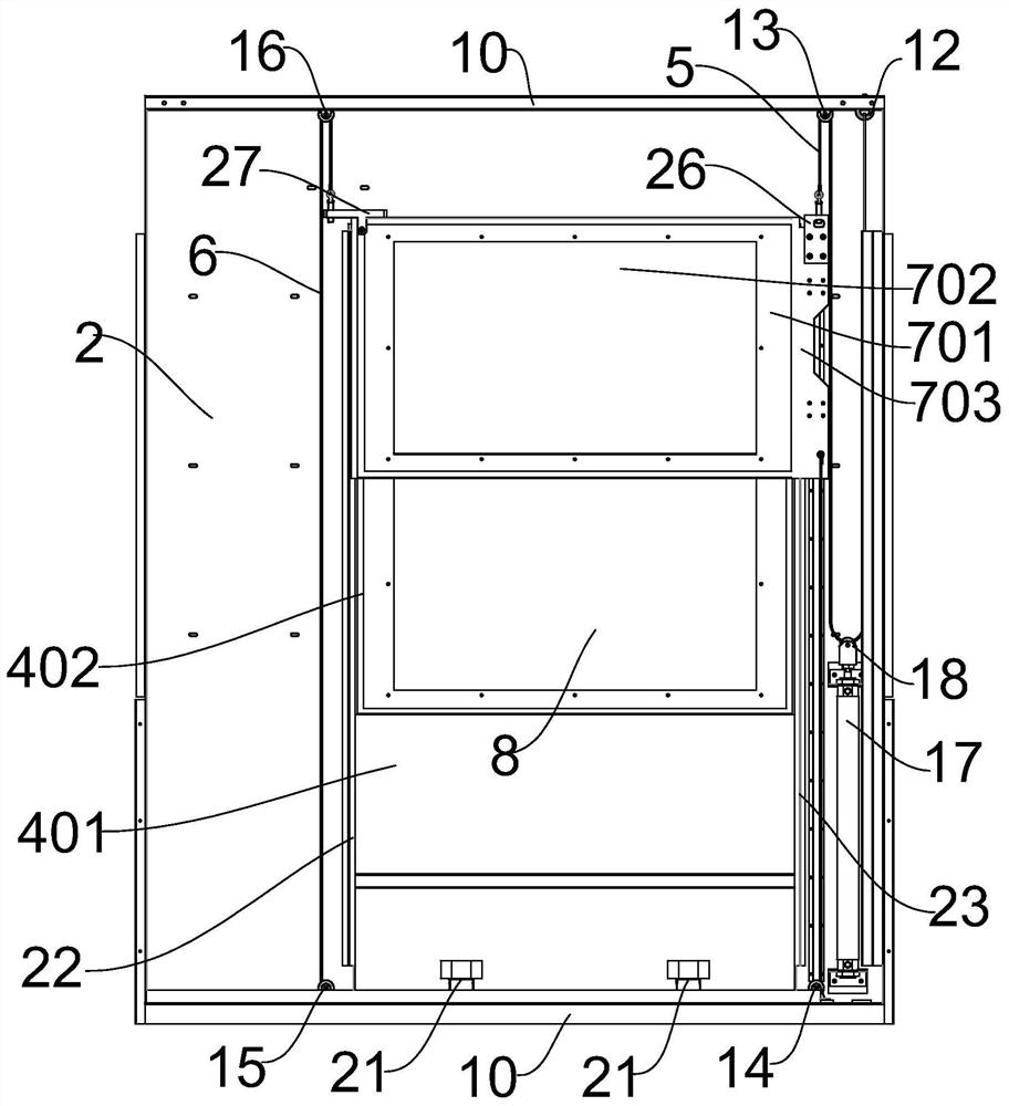
[0039] see Figure 1-18 , the present embodiment proposes an automatic lifting door mechanism, which is an integral part of the ...


PUM


Abstract

The invention discloses an automatic type lifting door mechanism. The automatic type lifting door mechanism comprises a supporting plate, a first steel wire, a second steel wire and a firs slide door,wherein the top of the supporting plate is equipped with a first fixed pulley and a fourth fixed pulley; the bottom of the supporting plate is equipped with a second fixed pulley and a third fixed pulley; the supporting plate is equipped with a gas cylinder; the piston rod end of the gas cylinder is fixedly connected to a movable slide wheel; the head end of the first steel wire is connected to the top of the supporting plate; the first steel wire winds across the movable pulley and the first fixed pulley in sequence, and is fixedly connected to the top end of one side of the first slide door; the head end of the second steel wire is connected to the bottom end of the first slide door; the second steel wire winds across the second fixed pulley, the third fixed pulley and the fourth fixedpulley in sequence, and is fixedly connected to the top end of the other side of the first slide door; while the gas cylinder drives the movable slide wheel to move in a height direction of the supporting plate, the first steel wire and the second steel wire drive the first slid door to move in a height direction of the supporting plate. The automatic type lifting door mechanism avoids asynchronism of dual-gas-cylinder drive, so that two steel wires are not stranded together mutually.

Description

technical field [0001] The invention relates to the technical field of pneumatic lifting doors, and more specifically relates to an automatic lifting door mechanism. Background technique [0002] With the development of the modern machining industry, the requirements for safety protection of machining equipment are constantly increasing, and the requirements for improving production efficiency, reducing production costs, and saving space are also increasing. When a piece of equipment (such as a wire cutting machine) requires a large feed door and there is not enough space, the demand for double-layer automatic lift doors is extremely urgent. Currently used automatic lift doors include a single cylinder for lifting and dual cylinders for lifting on both sides of the door. [0003] An overlapping pneumatic lifting door with the application number "201820454380.X" proposes a structure in which two cylinders are separately installed on both sides of the isolation door to lift t...

Claims


Application Information

Patent Timeline
Patent Type & Authority Applications(China)
IPC IPC(8): B23H7/02B23H11/00B23Q11/08
CPCB23H11/00B23H7/02B23Q11/08
Inventor 张则言阙彦王方正
Owner 力同机械自动化(上海)有限公司
Why Eureka
Try Eureka