Rotary knob assembly and washing machine using same

A washing machine and knob technology, applied in the field of washing machines, can solve problems such as unstable installation, poor rotation feel, and loud noise, and achieve the effects of reducing overall weight, easy operation and use, and light and smooth rotation

Active Publication Date: 2020-11-27
HEFEI HAIER DRUM WASHING MASCH CO LTD +1
View PDF4 Cites 2 Cited by
  • Summary
  • Abstract
  • Description
  • Claims
  • Application Information

AI Technical Summary

Problems solved by technology

However, the existing shaft encoders have the problems of large intermittent program selection span, large noise, large resistance and poor rotation feel.
[0003] To solve this problem, a shaftless encoder can be used to replace the traditional shafted encoder, but the structure of the knob corresponding to the shaftless encoder is more complicated, and because the electric control board and the surface of the casing have a certain distance, it is often necessary to set and encode The transmission part connected with the device, on this basis, a knob handle for the user to turn is added
At this time, if the knob cover is pasted on the top surface of the knob cover, the installation will be unstable due to the large connection gap between the knob cover and the knob body.
At the same time, due to the large diameter of the shaftless encoder, there is also the problem of laborious rotation

Method used


Image

  • Rotary knob assembly and washing machine using same
  • Rotary knob assembly and washing machine using same
  • Rotary knob assembly and washing machine using same

Examples


Embodiment 1

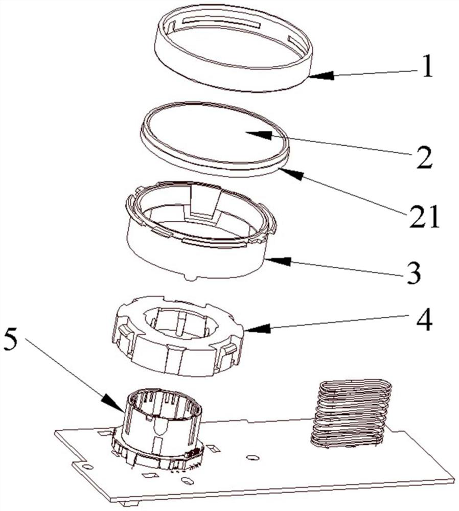
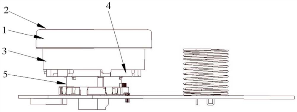
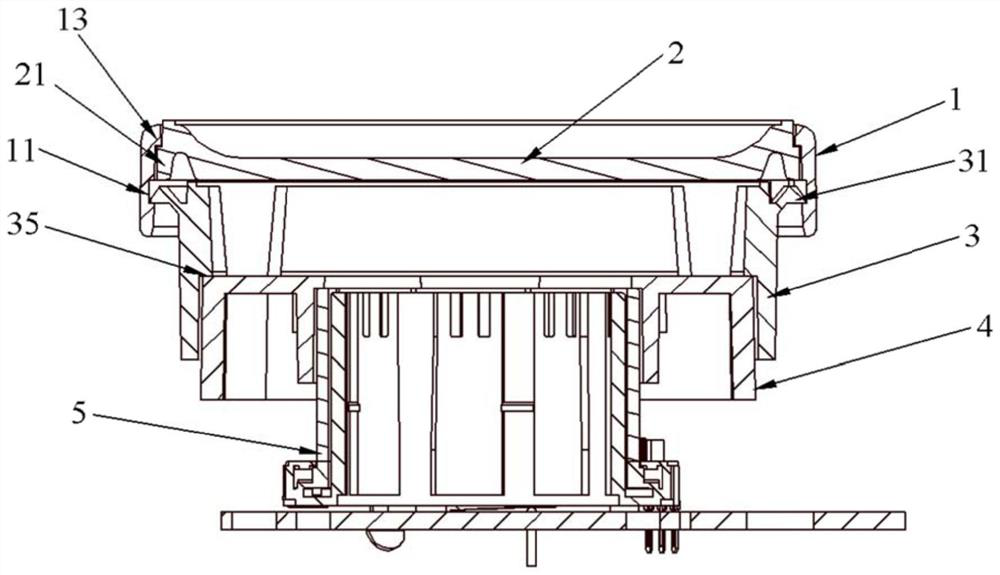
[0046] In this embodiment, a knob assembly is provided, which includes a knob body 3 arranged coaxially, a transmission member 4 and a shaftless encoder 5, and also includes a knob cover 2 and a ring for hooping the knob cover 2 on the top surface of the knob body 3. The knob ring 1, the knob ring 1, the knob body 3, the transmission member 4 and the shaftless encoder 5 are sequentially arranged layer by layer, so that the connection structure in the circumferential direction of the knob assembly is matched and hidden.

[0047] In this embodiment, the shaftless encoder is a standard part, installed on the control circuit board, and has a hollow inner and outer two-layer structure. The outer layer is a rotatable outer ring. The rotation of the outer ring can generate electrical signals and control the operation The mode is selected, and the inner layer is a fixed inner ring. In order to rotate the outer ring of the shaftless encoder, the present invention provides a hollow knob...

Embodiment 2

[0062] The difference between this embodiment and embodiment 1 is:

[0063] In this embodiment, the bottom of the second guide post 34 protrudes from the edge of the bottom surface of the knob body 3; since the guide and engagement structure is arranged on the periphery of the knob body, it is difficult to distinguish the installation position during assembly, so it is preferable to place the second guide post 34 The bottom protrudes from the edge of the bottom surface of the knob body, which is convenient for assemblers to align and install.

[0064] Other implementation modes of this embodiment are the same as embodiment 1.

Embodiment 3

[0066] The difference between this embodiment and embodiment 1 is:

[0067] In this embodiment, the top of the second guide column 34 is provided with a limiting card edge 35 extending along the inner circumference of the knob body 3; contact limit.

[0068] In this embodiment, the limiting card edge limits the position of the knob body in the axial direction of the knob assembly, and the installation structure is more compact and firm under the cooperation of the guide and the clamping structure.

[0069] Other implementation modes of this embodiment are the same as embodiment 1.


PUM


Abstract

The invention discloses a rotary knob assembly and a washing machine using the same. The rotary knob assembly comprises a rotary knob body, a transmission piece and a shaftless encoder which are coaxially arranged, and further comprises a rotary knob cover and a rotary knob ring used for hooping the rotary knob cover on the top face of the rotary knob body. The rotary knob ring, the rotary knob body, the transmission piece and the shaftless encoder are sleeved layer by layer in sequence, so that connecting structures in the circumferential direction of the rotary knob assembly are cooperatively hidden. According to the rotary knob assembly, on the basis of using the shaftless encoder, the ring structure used for fixing the rotary knob cover and the rotary knob body is added, on one hand, the effect of sealing the rotary knob cover and the rotary knob body is improved, and on the other hand, the moment of the rotary knob is improved. The problems that in an existing rotary knob assembly, the rotating noise is large, the resistance is high, and the handfeeling of a user is poor are solved, and the rotary knob assembly is suitable for application and popularization.

Description

technical field [0001] The invention belongs to the technical field of household appliances, and in particular relates to a knob assembly and a washing machine using the same. Background technique [0002] With the development of home appliance technology, the logic of user operation panels has become more and more simplified. From the early multiple operation knobs to the structure of knobs and simple cases with panel display, the reduction in the number of knobs also makes the knobs correspond to selection functions. The increase in the number of knobs also increases the frequency of use of the knobs. However, the existing encoder with a shaft has the problems of large intermittent program selection span, high noise, large resistance and poor rotation feel. [0003] To solve this problem, a shaftless encoder can be used to replace the traditional shafted encoder, but the structure of the knob corresponding to the shaftless encoder is relatively complicated, and because th...

Claims


Application Information

Patent Timeline
Patent Type & Authority Applications(China)
IPC IPC(8): D06F34/30D06F34/34
Inventor 庄德永刘真良张志强李丽平程宝珍
Owner HEFEI HAIER DRUM WASHING MASCH CO LTD
Why Eureka
Try Eureka