
Sublimation dehydration device

A dehydration device and supply device technology, applied in the direction of drying solid materials, drying solid materials without heating, lighting and heating equipment, etc., can solve the problems of time sensitivity reduction, affecting the sublimation and dehydration process of frozen-thawed materials, and achieve temperature control sensitive effect

Inactive Publication Date: 2020-11-27
广州蓝日生物科技有限公司
View PDF5 Cites 0 Cited by
  • Summary
  • Abstract
  • Description
  • Claims
  • Application Information

AI Technical Summary

Problems solved by technology

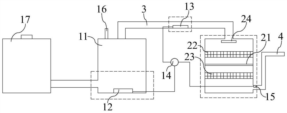
[0002] The commonly used dehydration method for frozen-thawed materials such as frozen-thawed cells is to place the frozen-thawed materials in an atmospheric nitrogen environment, control the temperature rise and fall of the nitrogen gas, sublimate the solid water in the frozen-thawed materials, and dehydrate the frozen-thawed materials. This method corresponds to In the sublimation dehydration device, the controller controls the evaporator to evaporate liquid nitrogen to create a nitrogen environment, and controls the heater to control the temperature of the nitrogen in the sublimation chamber to achieve normal pressure sublimation dehydration of the frozen-thawed materials in the sublimation chamber; however, the existing The inner wall of the vacuum tube in the sublimation dehydration device is directly in contact with nitrogen, and the heat contained in the heated nitrogen is directly absorbed by the inner wall, which reduces the time sensitivity of nitrogen temperature control and affects the sublimation and dehydration process of frozen-thawed materials.

Method used


Image

  • Sublimation dehydration device
  • Sublimation dehydration device
  • Sublimation dehydration device

Examples


Embodiment Construction

[0020] The specific implementation manners of the present invention will be further described in detail below in conjunction with the accompanying drawings and embodiments. The following examples are used to illustrate the present invention, but are not intended to limit the scope of the present invention.

[0021] In the description of the present invention, it should be understood that the terms "first", "second", etc. are used in the present invention to describe various information, but these information should not be limited to these terms, and these terms are only used to describe the same type of information are separated from each other. For example, "first" information may also be referred to as "second" information without departing from the scope of the present invention, and similarly, "second" information may also be referred to as "first" information.

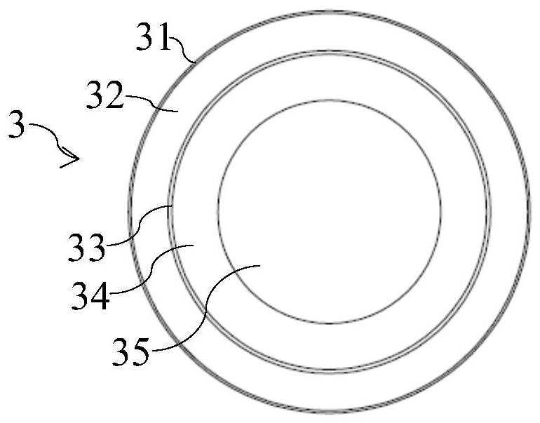
[0022] Such as Figure 1-Figure 3 As shown, a sublimation dehydration device in a preferred embodiment of the...


PUM


Abstract

The invention discloses a sublimation dehydration device. The sublimation dehydration device comprises a heating supply device, a sublimation work box, and a vacuum pipe which comprises an outer pipeand an inner pipe sleeved with the outer pipe, a vacuum layer is arranged between the outer pipe and the inner pipe, an inner cavity is formed in the inner pipe, and a heat insulation layer is arranged between the inner pipe and the inner cavity; two ends of the vacuum pipe respectively communicate with the heating supply device and the sublimation working box; wherein the heating supply device isused for heating gaseous nitrogen and conveying the heated gaseous nitrogen to the sublimation working box along the inner cavity, and the gaseous nitrogen flows in the sublimation working box and covers the surface of a freeze-thawed material; the pipe body structure of the vacuum pipe is provided with the outer pipe and the inner pipe, the vacuum layer is arranged between the outer pipe and theinner pipe, the inner cavity is formed in the inner pipe, the heat insulation layer is arranged in the inner cavity, heat exchange between gaseous nitrogen and the inner wall can be effectively blocked, and temperature control over the gaseous nitrogen is more sensitive.

Description

technical field [0001] The invention relates to the technical field of cell preservation, in particular to a sublimation dehydration device. Background technique [0002] The commonly used dehydration method for frozen-thawed materials such as frozen-thawed cells is to place the frozen-thawed materials in an atmospheric nitrogen environment, control the temperature rise and fall of the nitrogen gas, sublimate the solid water in the frozen-thawed materials, and dehydrate the frozen-thawed materials. This method corresponds to In the sublimation dehydration device, the controller controls the evaporator to evaporate liquid nitrogen to create a nitrogen environment, and controls the heater to control the temperature of the nitrogen in the sublimation chamber to achieve normal pressure sublimation dehydration of the frozen-thawed materials in the sublimation chamber; however, the existing The inner wall of the vacuum tube in the sublimation dehydration device is directly in cont...

Claims


Application Information

Patent Timeline
Patent Type & Authority Applications(China)
IPC IPC(8): F26B5/04F26B25/00
CPCF26B5/04F26B25/00
Inventor 徐小杨
Owner 广州蓝日生物科技有限公司
Learn More