Directional solidification device and method for high-temperature alloy

A directional solidification, high temperature alloy technology, applied in the field of metal casting, can solve the problems of freckles of crystal structure, uneven heat dissipation of anchor-shaped mold shells, waste of crystals and miscellaneous crystal content, etc., to avoid freckles, simple structure, and solve the effect of heat dissipation.

Active Publication Date: 2021-10-19
XI AN JIAOTONG UNIV
View PDF5 Cites 0 Cited by
  • Summary
  • Abstract
  • Description
  • Claims
  • Application Information

AI Technical Summary

Problems solved by technology

[0008] In order to overcome the shortcomings of the above-mentioned prior art, the object of the present invention is to provide a superalloy directional solidification device, which aims to solve the defect problems such as freckles in the crystal structure caused by uneven heat dissipation of the anchor formwork in the prior art, superalloy The waste of crystals in the directional solidification process and the high content of miscellaneous crystals in the superalloy directional solidification process and other technical problems

Method used


Image

  • Directional solidification device and method for high-temperature alloy
  • Directional solidification device and method for high-temperature alloy
  • Directional solidification device and method for high-temperature alloy

Examples


Embodiment 1

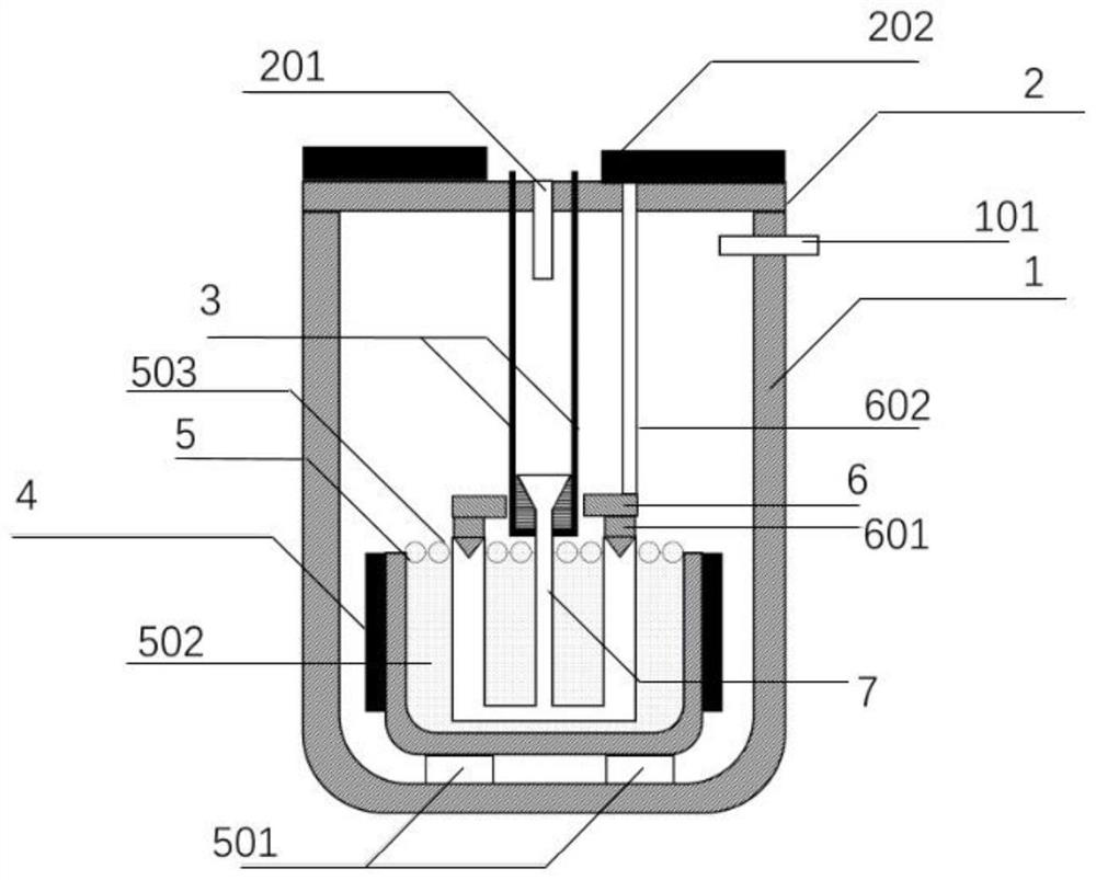
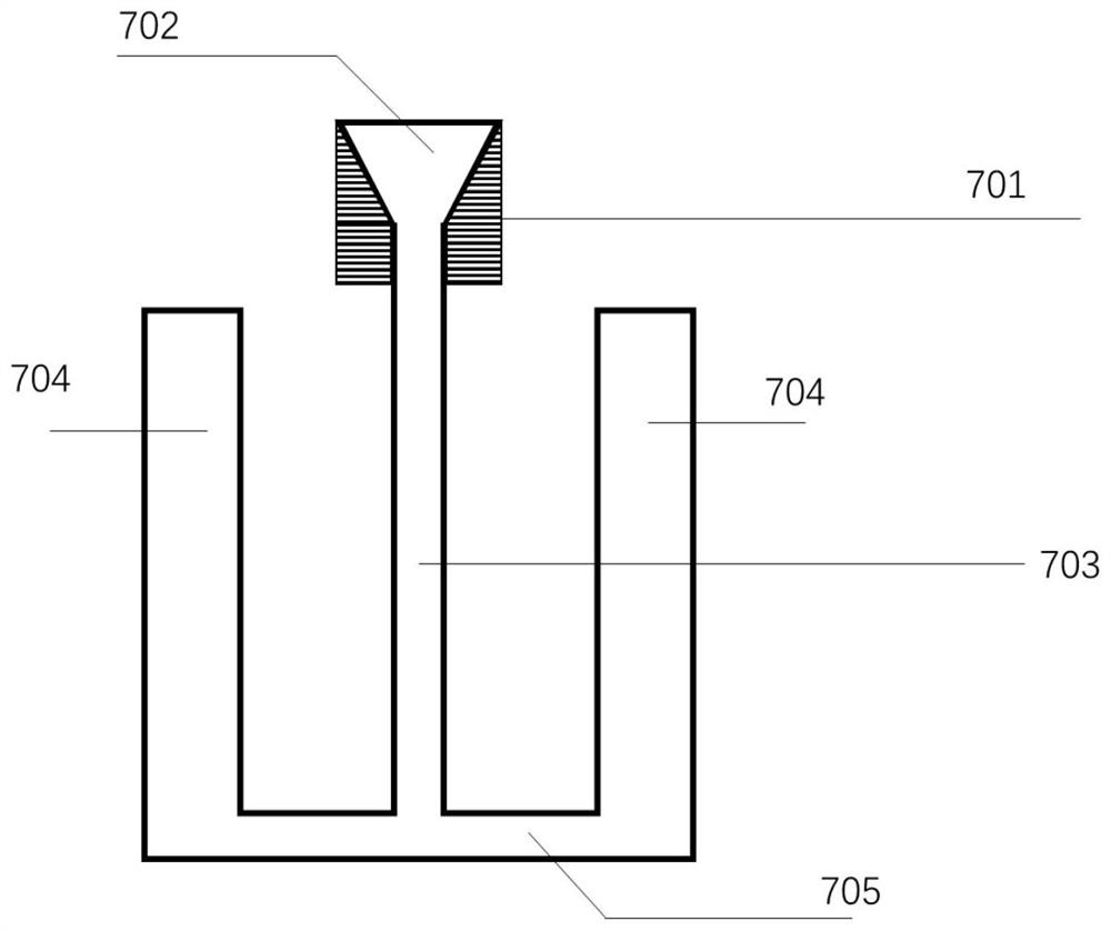
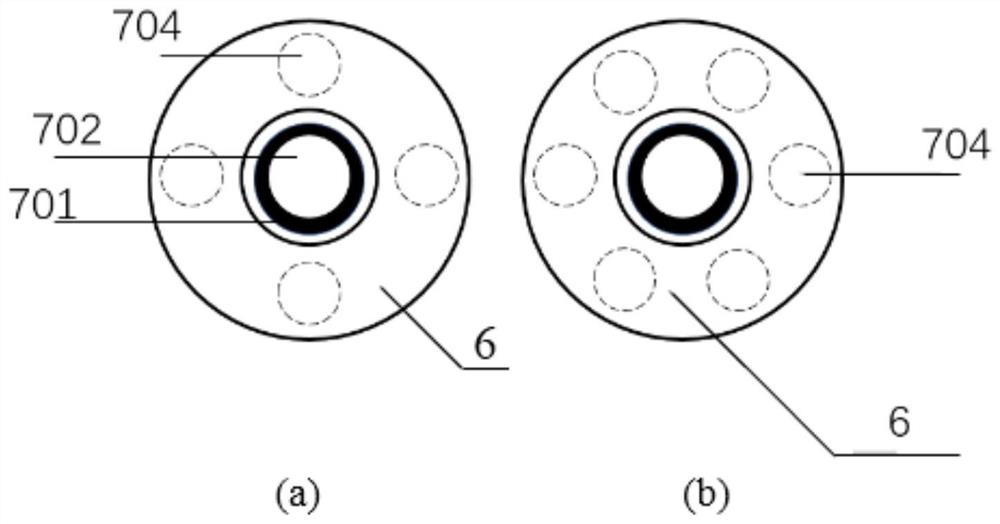
[0068] CMSX-4 alloy is selected as the experimental material, aluminum block is selected as constant temperature fluid 502, alumina ceramic sheet (10mm) is selected as thermal insulation float 503, alumina ceramic anchor mold shell 7 is selected, and 4 rows of alloy mold 704 are selected. Cloth, keep the constant temperature fluid 502 to 1450 ℃, and the alloy liquid casting temperature is 1500 ℃. After the alloy liquid is completely filled, the upward pulling speed is controlled to 1mm / min for upward solidification. The experiment shows that among the four alloy molds 704 A small amount of impurity crystals were found in the single crystal samples.

Embodiment 2

[0070] Choose CMSX-4 alloy as the experimental material, choose aluminum block as constant temperature fluid 502, choose alumina ceramic ball (10mm) as heat insulation float 503, choose alumina ceramic anchor mold shell 7, choose 6 rows of alloy mold 704 Cloth, keep the constant temperature fluid 502 to 1500 ℃, the alloy liquid casting temperature is 1500 ℃, after the alloy liquid is completely filled, the upward pulling speed is controlled to 2mm / min for upward solidification. The experiment shows that only one alloy mold 704 A small amount of impurity crystals were found in the single crystal samples.

Embodiment 3

[0072] CMSX-4 alloy is selected as the experimental material, copper block is selected as constant temperature fluid 502, alumina ceramic sheet (5mm) is selected as thermal insulation float 503, alumina ceramic anchor mold shell 7 is selected, and 4 rows of alloy mold 704 are selected. Cloth, the constant temperature fluid 502 is kept at 1500 ℃, and the alloy liquid casting temperature is 1550 ℃. After the alloy liquid is completely filled, the upward pulling speed is controlled to 3mm / min for upward solidification. The experiment shows that no miscellaneous crystals are found.


PUM

PropertyMeasurementUnit
sizeaaaaaaaaaa

Abstract

The invention discloses a directional solidification device and method for high-temperature alloy, belonging to the technical field of metal casting. The invention aims to solve the defect problems of freckles and the like in a crystal structure caused by non-uniform heat dissipation of an anchor-shaped mold shell and the problem of crystal waste in the directional solidification process of the high-temperature alloy. According to the invention, the heat preservation or overheating state of alloy liquid can be achieved through a heater, the anchor-shaped mold shell is lifted upwards at a constant speed through a lifting rod, then a water cooling system is arranged on the anchor-shaped mold shell, and at the moment, a constant-temperature fluid gradually emerges from the anchor-shaped mold shell, so a part of heat of the liquid level is dissipated, a temperature gradient is generated, and the alloy liquid in contact with a sub-crystal is forced to directionally solidify downwards to form a single crystal; and therefore, the heat dissipation problem of the anchor-shaped mold shell can be effectively solved, the defect problems such as freckles in a crystal structure are also avoided, and crystal wasting in the directional solidification process is reduced.

Description

technical field [0001] The invention belongs to the field of metal casting, and relates to a high-temperature alloy directional solidification device and a solidification method. Background technique [0002] Superalloys are a kind of important Ni-based metal materials used in the core components of gas turbines and aerospace engines. They can maintain good strength, stiffness, creep resistance, corrosion resistance and other excellent properties under high temperature service conditions. Physicochemical properties. At present, most of the commonly used superalloys are deformation, solid solution, aging, powder superalloys, such as the typical Inconel718, which can maintain good comprehensive performance at 650 degrees Celsius. [0003] However, at higher temperatures (for example, the temperature of the combustion chamber in front of a modern aero-engine turbine has exceeded 1400 degrees Celsius, and even under the action of heat-resistant coatings and air cooling, the tem...

Claims


Application Information

Patent Timeline
Patent Type & Authority Applications(China)
IPC IPC(8): C30B29/52C30B11/00
CPCC30B29/52C30B11/002C30B11/003C30B11/006
Inventor 王富刘洋张碧璇段倩杨强
Owner XI AN JIAOTONG UNIV
Why Eureka
Try Eureka