
Offset imaging method and device for undulating surface

A technology of undulating surface and migration imaging, applied in measurement devices, seismology, geophysical measurement, etc., can solve problems such as affecting imaging accuracy

Pending Publication Date: 2020-11-27
BC P INC CHINA NAT PETROLEUM CORP +1
View PDF3 Cites 0 Cited by
  • Summary
  • Abstract
  • Description
  • Claims
  • Application Information

AI Technical Summary

Problems solved by technology

Therefore, on undulating surfaces such as mountains, using the wave field continuation migration under the condition of a unified horizontal datum will affect the accuracy of imaging

Method used


Image

  • Offset imaging method and device for undulating surface
  • Offset imaging method and device for undulating surface
  • Offset imaging method and device for undulating surface

Examples


Embodiment Construction

[0026] For purposes of embodiments of the present invention, the technical solution and merits thereof more apparent, the following embodiments in conjunction with the accompanying drawings described in further detail embodiments of the present invention. In this exemplary embodiment of the present invention are used to explain the present invention but are not intended to limit the present invention.

[0027] In the description of the present specification, the "comprises", "comprising", "having", "containing" and the like, are open-ended terms, i.e., to mean including but not limited to. Reference term "one embodiment," "one embodiment," "some embodiments," "example," etc. means that a particular described feature of the exemplary embodiment or embodiments described herein, structure, or characteristic is included in at least one application of the present embodiments or examples. In the present specification, the meaning of the above term is not necessarily referred to as the s...


PUM


Abstract

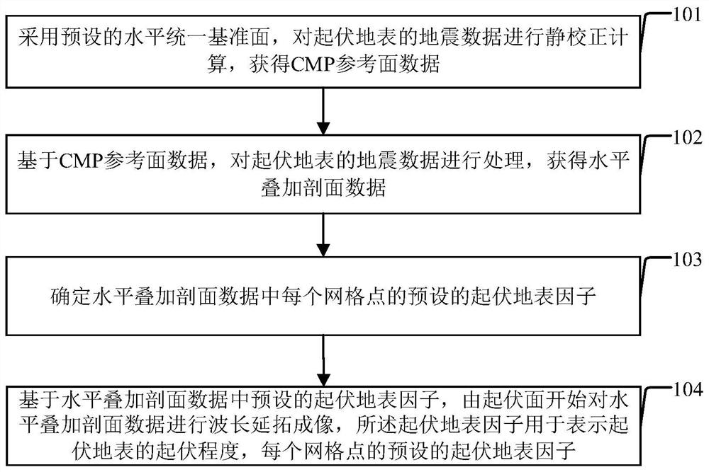
The invention provides a migration imaging method and device for an undulating surface. The method comprises the steps: carrying out static correction calculation of seismic data of a rugged surface through a preset horizontal unified reference surface, and obtaining CMP reference surface data; processing the seismic data of the rugged surface based on the CMP reference surface data to obtain horizontal stacking profile data; determining a preset rugged surface factor of each grid point in the horizontal superposition profile data; and carrying out wavelength continuation imaging on the horizontal superposition profile data from the rugged surface based on a preset fluctuating surface factor in the horizontal superposition profile data, and using the rugged factor for representing the rugged degree of the rugged surface and presetting the rugged surface factor of each grid point. According to the invention, migration imaging on the rugged surface can be realized, and the imaging precision is high.

Description

Technical field [0001] The present invention relates to the field of imaging processing, and more particularly to a method and an offset image forming apparatus rugged surface. Background technique [0002] Currently, the offset undulating surface imaging process, i.e. wavefield extrapolation offset process, generally require being horizontal offset, and the offset to be zero in the excitation and reception surface. In the complex surface area large height difference is difficult to satisfy these requirements, available time shift method statics correcting the seismic data to a horizontal reference plane, due to the time shift method statics only made in the vertical direction shift, without considering the direction of propagation, thus changing the nature of the original time profile of the hyperbolic diffraction waves, poor convergence after migration, and therefore this method is approximate only at the surface with a high level of uniform reference plane the difference is sm...

Claims


Application Information

Patent Timeline
IPC IPC(8): G01V1/30G01V1/36
CPCG01V1/301G01V1/362G01V2210/53G01V2210/74
Inventor 金守利钱忠平孙鹏远田振平岳玉波
Owner BC P INC CHINA NAT PETROLEUM CORP
Learn More