Isolating switch operating mechanism with modularly designed control loop and using method

A modular design and isolating switch technology, applied in the direction of air switch components, etc., can solve the problems of relays and secondary components and contacts, low work efficiency, high failure rate of equipment operation, etc., to reduce contact with live secondary lines risks, reduce equipment utilization, and optimize operating procedures

Active Publication Date: 2020-11-27
GUIZHOU POWER GRID CO LTD
View PDF9 Cites 0 Cited by
  • Summary
  • Abstract
  • Description
  • Claims
  • Application Information

AI Technical Summary

Problems solved by technology

[0002] The electric operating mechanism is widely used in isolating switches to drive the isolating switch to perform opening and closing operations. At present, the opening and closing position signals of the electric operating mechanism of the isolating switch box are sent by the auxiliary switch. The auxiliary switches are all switched before the mechanism is in place. Accurately send out the opening and closing signals of the mechanism; the mechanism box is made of stainless steel, and only a heater is installed inside without any other treatment. It is easy to cause condensation, internal electrical components and mechanical parts to corrode and jam under high temperature and high humidity conditions. The service life of the equipment is shortened, and the failure rate of the equipment is high; the secondary control circuit of the electric operating mechanism mainly realizes the opening and closing operation of the isolating switch through the mutual logical interlocking of the relays, and the use of relays, secondary components and contacts is more, and the failure rate is high , and troubleshooting after a failure requires professionals to troubleshoot according to the drawings, the troubleshooting time is long, and the secondary wiring of each relay is fixed with bolts, it is troublesome to disassemble and assemble damaged components, and the work efficiency is low.

Method used


Image

  • Isolating switch operating mechanism with modularly designed control loop and using method
  • Isolating switch operating mechanism with modularly designed control loop and using method
  • Isolating switch operating mechanism with modularly designed control loop and using method

Examples


Embodiment

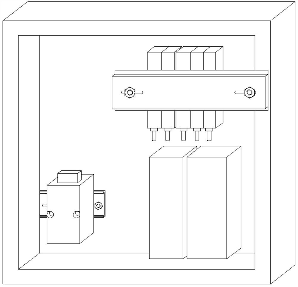
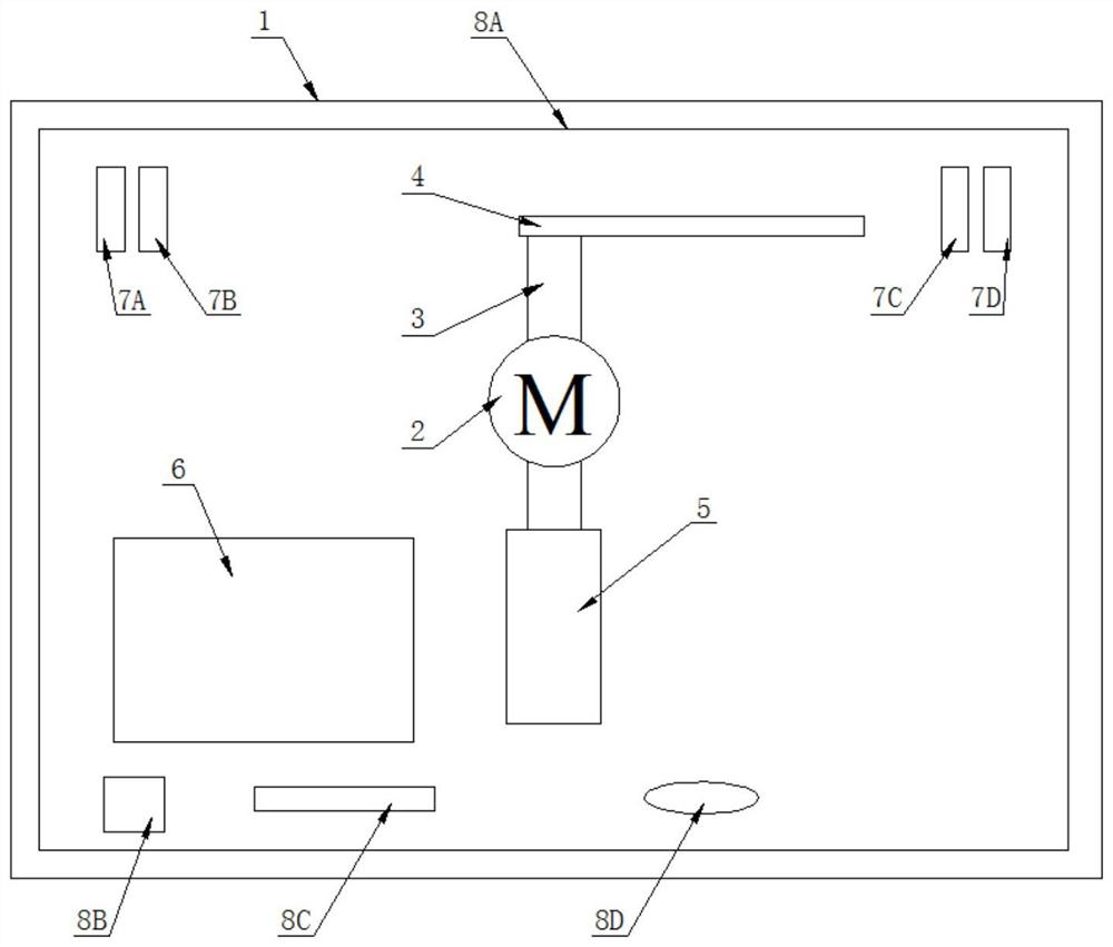
[0046] refer to figure 1 , the present embodiment provides an isolating switch operating mechanism with a modular control circuit design; it includes an isolating switch operating mechanism with a modular control circuit design, which includes a box 1 with a cover; inside the box 1 The motor 2 and the output end of the motor 2 are respectively connected to the input end of the action unit 4 and the auxiliary switch assembly 5 through the transmission device 3; the motor 2 is connected to the control unit 6 through a wire, and is controlled by the control unit 6; the control unit 6 respectively electrically connected with the auxiliary switch assembly 5, the opening and closing assembly 7 and the temperature control assembly 8;

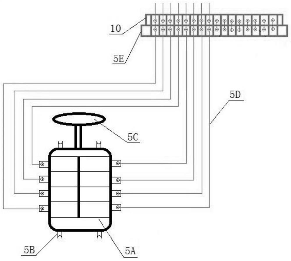
[0047] The auxiliary switch assembly 5 includes an auxiliary switch body 5A; the auxiliary switch body 5A is provided with a fixing seat 5B and a connecting flange 5C for detachable installation with the box body 1; the auxiliary switch body 5A is also...


PUM


Abstract

The invention discloses an isolating switch operating mechanism with a modularly designed control loop, which comprises a box body with a cover plate, a motor is arranged in the box body, and the output end of the motor is connected with the input ends of the action unit and the auxiliary switch assembly through a transmission device; the motor is connected with the control unit through a wire andcontrolled by the control unit. The control unit is electrically connected with the auxiliary switch assembly, the opening and closing assembly and the temperature control assembly. According to themechanism disclosed in the invention, the problem of the isolation switch operation box at present is effectively solved.

Description

technical field [0001] The invention relates to the technical field of isolating switch devices, in particular to an isolating switch operating mechanism with a modular design of a control loop and a method for using it. Background technique [0002] The electric operating mechanism is widely used in isolating switches to drive the isolating switch to perform opening and closing operations. At present, the opening and closing position signals of the electric operating mechanism of the isolating switch box are sent by the auxiliary switch. The auxiliary switches are all switched before the mechanism is in place. Accurately send out the opening and closing signals of the mechanism; the mechanism box is made of stainless steel, and only a heater is installed inside without any other treatment. It is easy to cause condensation, internal electrical components and mechanical parts to corrode and jam under high temperature and high humidity conditions. The service life of the equip...

Claims


Application Information

Patent Timeline
Patent Type & Authority Applications(China)
IPC IPC(8): H01H31/02H01H31/10
CPCH01H31/02H01H31/10
Inventor 苏剑锋张津林顺生胡诚邓昭辉赵松吴英帅卢森微丁宇洁
Owner GUIZHOU POWER GRID CO LTD
Why Eureka
Try Eureka