


Quick Research
Generate reliable direction feasibility study reports for your R&D in just a few steps.

Technical Q&A
Discover and master advanced knowledge NOW. Basics, ideas, possibilities, all at once.

Find Solutions
As an expert in R&D theories, this can generate solutions to your technical problems instantly.

Evaluate Feasibility
Analyze your overall solution with one click, know your potential R&D risks in advance.

Monitor Landscape
Get weekly tech updates, stay abreast of the latest tech innovations and key insights.
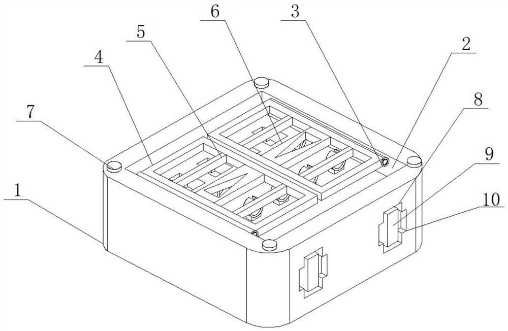
Wireless signal remote transceiving system
A technology for remote sending and receiving and wireless signals, applied in transmission systems, electrical components, etc., can solve problems such as shock absorption, large space occupation, inconvenient use, etc., and achieve the effects of avoiding damage, prolonging service life, and preventing falling off
- Summary
- Abstract
- Description
- Claims
- Application Information
AI Technical Summary
Problems solved by technology
Method used
Image

Examples
Embodiment approach
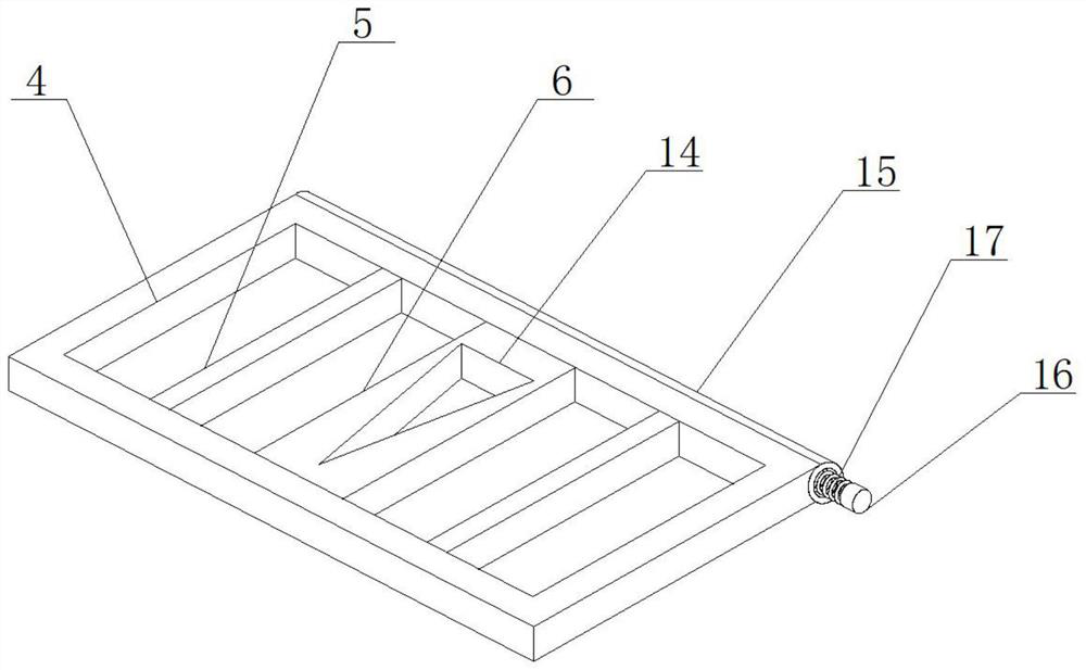
[0027] As a preferred embodiment of the present invention, one end of the antenna 9 is equipped with a fixed lug 18, and a slider 19 is installed on the fixed lug 18, and the slider 19 and the fixed lug 18 are rotated Shaft 20 is connected.
[0028] As a preferred embodiment of the present invention, a limiting block 21 is installed on the slider 19, a limiting groove is provided on the inner wall of the cavity 8, and the limiting block 21 is installed inside the limiting groove.
[0029] As a preferred embodiment of the present invention, a base 7 is provided inside the box 1, and the base 7 is made of rubber.
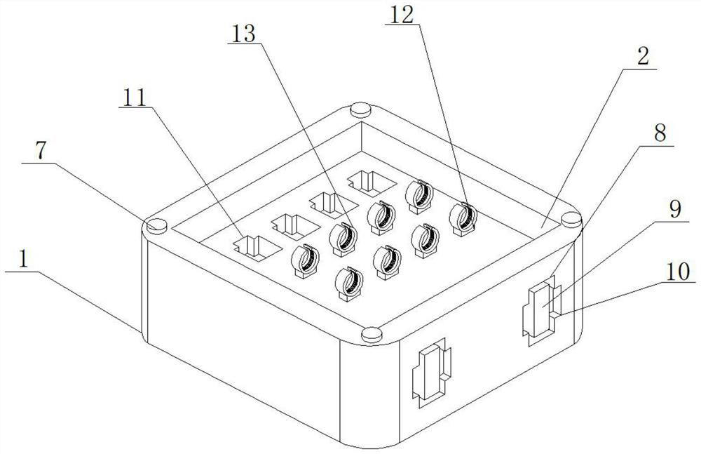
[0030] As a preferred embodiment of the present invention, the fixing ring 13 is provided with an opening 22 , and the inner wall of the opening 22 is provided with a mounting groove 23 , and a limiting ring 24 is installed inside the mounting groove 23 .
[0031] As a preferred embodiment of the present invention, the limiting ring 24 is provided with an opening two...
PUM
 Abstract
Description
Claims
Application Information
 - R&D Engineer
- R&D Manager
- IP Professional
- Industry Leading Data Capabilities
- Powerful AI technology
- Patent DNA Extraction
Browse by: Latest US Patents, China's latest patents, Technical Efficacy Thesaurus, Application Domain, Technology Topic, Popular Technical Reports.
© 2024 PatSnap. All rights reserved.Legal|Privacy policy|Modern Slavery Act Transparency Statement|Sitemap|About US| Contact US: help@patsnap.com