Dispersing device for ink production

A technology of dispersing device and ink, applied in mixers with rotary stirring device, transportation and packaging, dissolving and other directions, can solve the problems of not fully achieving 100% contact, reducing heat transfer effect, poor separation effect, etc. Heating effect, improved dispersion effect, improved contact area effect

Inactive Publication Date: 2020-12-01
赖胡英
View PDF0 Cites 0 Cited by
  • Summary
  • Abstract
  • Description
  • Claims
  • Application Information

AI Technical Summary

Problems solved by technology

[0003] The existing separation device for ink production needs to be heated during the ink separation process. However, the heating device can only be installed on the inner wall of the treatment box and cannot completely contact the separated ink. It can't fully achieve 100% contact even when stirring. At the same time, the existing stirring equipment can only achieve a partial stirring effect, resulting in poor separation effect and indirectly reducing the heat transfer effect.

Method used


Image

  • Dispersing device for ink production
  • Dispersing device for ink production
  • Dispersing device for ink production

Examples


Embodiment 1

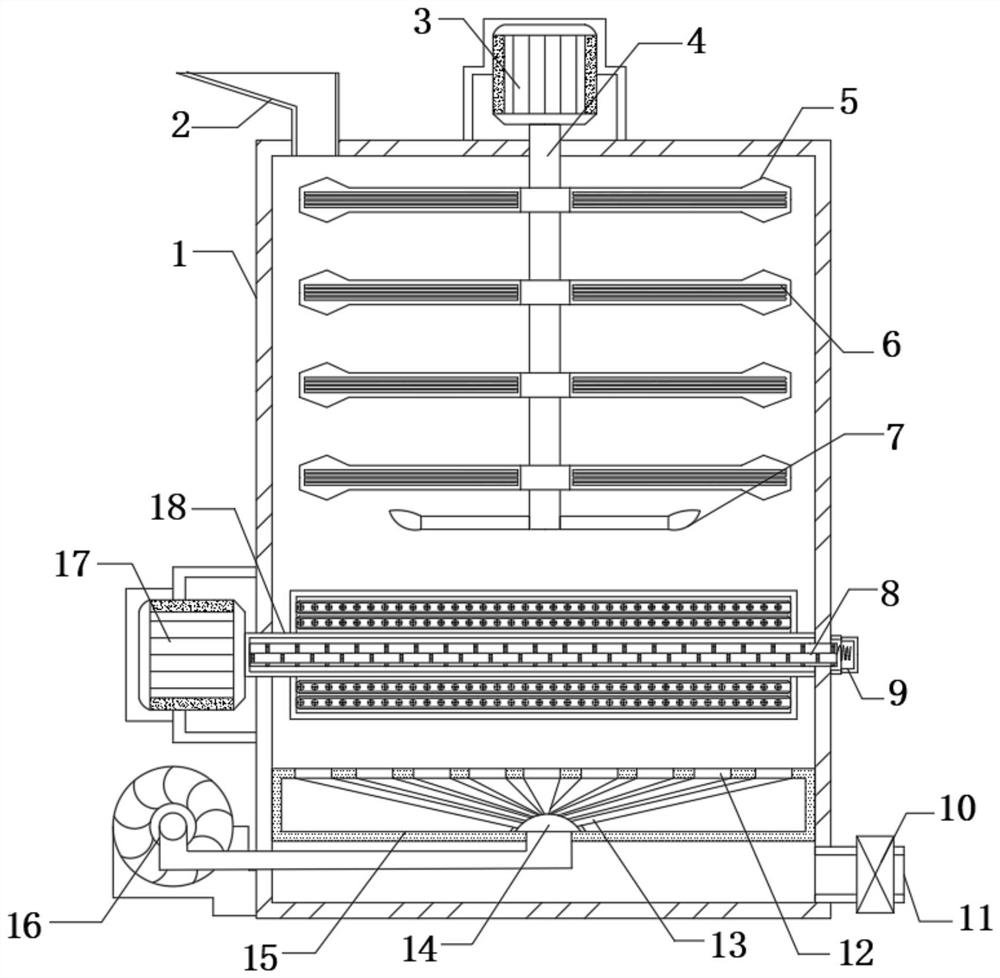
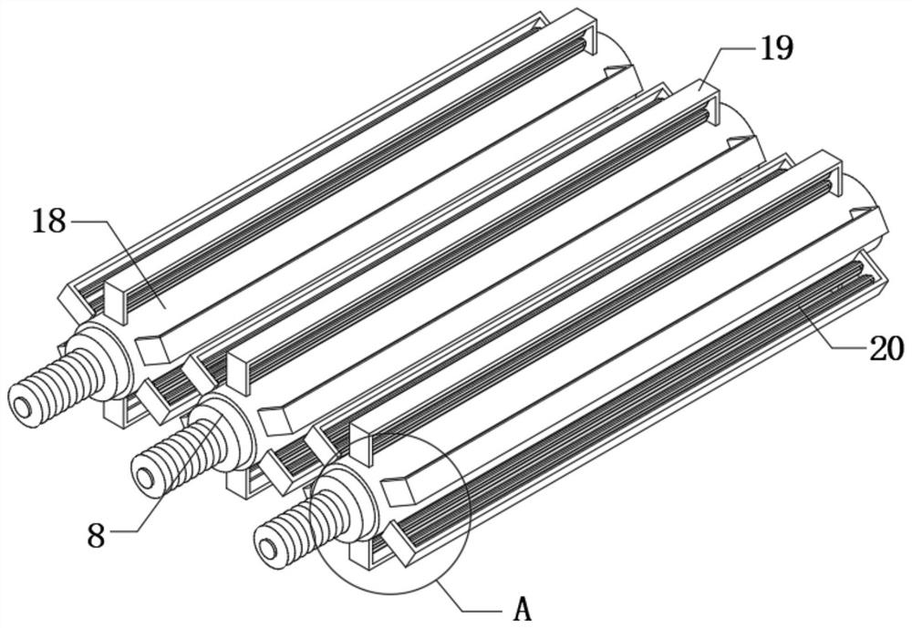
[0027] refer to Figure 1-4 , a dispersing device for ink production, comprising a treatment box 1, the outer wall of one side of the treatment box 1 is equidistantly fixedly connected with No. 2 motor 17, and the output shaft of each No. 2 motor 17 is fixedly connected with a heat conducting The sleeve 18, the inner wall of the treatment box 1 located inside each heat conduction sleeve 18 is fixedly connected with an electric heating tube 8, and the outer wall of the treatment box 1 located at the outside of a plurality of electric heating tubes 8 is fixedly connected with the same line sleeve 9, which conducts heat. The outer wall of the sleeve 18 is equidistantly fixedly connected with the cutting frame 19, and the inner wall of each cutting frame 19 is connected with the spin shaft 20 through a bearing.

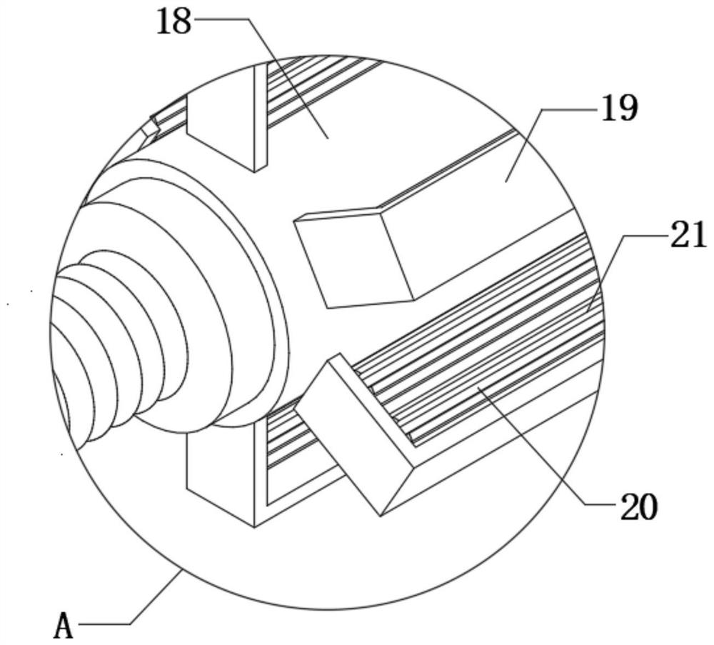
[0028] In the present invention, the outer wall of the spin shaft 20 is fixedly connected with the slitting leaves 21 equidistantly, and the outer wall of each slitting l...

Embodiment 2

[0036] refer to Figure 1-5 , a dispersing device for ink production, comprising a treatment box 1, the outer wall of one side of the treatment box 1 is equidistantly fixedly connected with No. 2 motor 17, and the output shaft of each No. 2 motor 17 is fixedly connected with a heat conducting Sleeve 18, the inner wall of the processing box 1 located inside each heat conducting sleeve 18 is fixedly connected with an electric heating tube 8, and the outer wall of the processing box 1 located at the outside of a plurality of electric heating tubes 8 is fixedly connected with the same line sleeve 9, heat conduction The outer wall of the sleeve 18 is equidistantly fixedly connected with the cutting frame 19, and the inner wall of each cutting frame 19 is connected with the spin shaft 20 through a bearing.

[0037] In the present invention, the outer wall of the spin shaft 20 is equidistantly fixedly connected with the slitting leaves 21, and the outer wall of each slitting leaf 21 ...


PUM


Abstract

The invention belongs to the technical field of ink production. The invention relates to a dispersing device for ink production. An existing separation device for printing ink production needs to be heated in the printing ink separation process, however, a heating device can only be installed on the inner wall of a treatment box. In order to solve the problems that the existing stirring equipmentcan not be in complete contact with the separated printing ink, stirring equipment can not realize complete 100% contact when stirring the printing ink, and the existing stirring equipment can only play a part of stirring effect, so that the separation effect is poor, and the heat transfer effect is indirectly reduced, the following scheme is provided that: the dispersing device comprises a treatment box. By arranging a heat conduction sleeve, a second motor and an electric heating pipe, when rotary dispersion operation is carried out, the electric heating pipe is placed in the heat conductionsleeve, and when ink passes through the heat conduction sleeve, the heat conduction sleeve distributed at equal intervals heats and disperses the ink, so that the contact area is increased, and the dispersion effect is improved.

Description

technical field [0001] The invention relates to the technical field of ink production, in particular to a dispersing device for ink production. Background technique [0002] Ink is an important material for printing. It expresses patterns and characters on the substrate by printing or inkjet painting. The ink includes main components and auxiliary components, which are uniformly mixed and rolled repeatedly to form a viscous colloidal fluid, which needs to be dispersed by a dispersing device during the ink production process. [0003] The existing separation device for ink production needs to be heated during the ink separation process. However, the heating device can only be installed on the inner wall of the treatment box and cannot completely contact the separated ink. It can't fully achieve 100% contact even when it is stirred. At the same time, the existing stirring equipment can only achieve a partial stirring effect, resulting in poor separation effect and indirectly ...

Claims


Application Information

Patent Timeline
Patent Type & Authority Applications(China)
IPC IPC(8): B01F7/18B01F13/02B01F15/06B01F7/04B01F33/40
CPCB01F27/2323B01F27/191B01F27/70B01F33/402B01F33/4094B01F27/90B01F35/90B01F2035/99B01F2101/35
Inventor 赖胡英
Owner 赖胡英
Why Eureka
Try Eureka