Pipe cutting device

A cutting device and pipe technology, applied in the direction of pipe shearing device, shearing device, feeding device, etc., can solve the problems of large harm to operators, small particles, and difficult collection.

Pending Publication Date: 2020-12-01
ANHUI TSP ULTRA PRECISION MOLD
View PDF0 Cites 2 Cited by
  • Summary
  • Abstract
  • Description
  • Claims
  • Application Information

AI Technical Summary

Problems solved by technology

[0002] Cutting machines are widely used in modern production. Many products need to use cutting machines in the process of processing. In many cases, cutting machines are used to cut pipes and other materials during the cutting process. It can still be used. At the same time, these wastes are often small in size after cutting and other operations, making them easy to scatter in the air. Not only is it difficult to collect, but it is also more harmful to operators.

Method used


Image

  • Pipe cutting device
  • Pipe cutting device

Examples


Embodiment Construction

[0038] Specific embodiments of the present invention will be described in detail below in conjunction with the accompanying drawings. It should be understood that the specific embodiments described here are only used to illustrate and explain the present invention, and are not intended to limit the present invention.

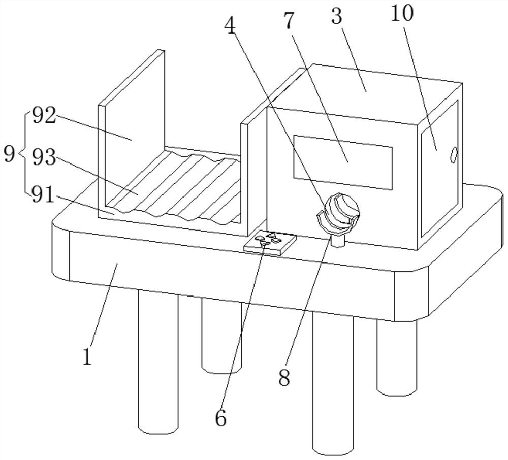
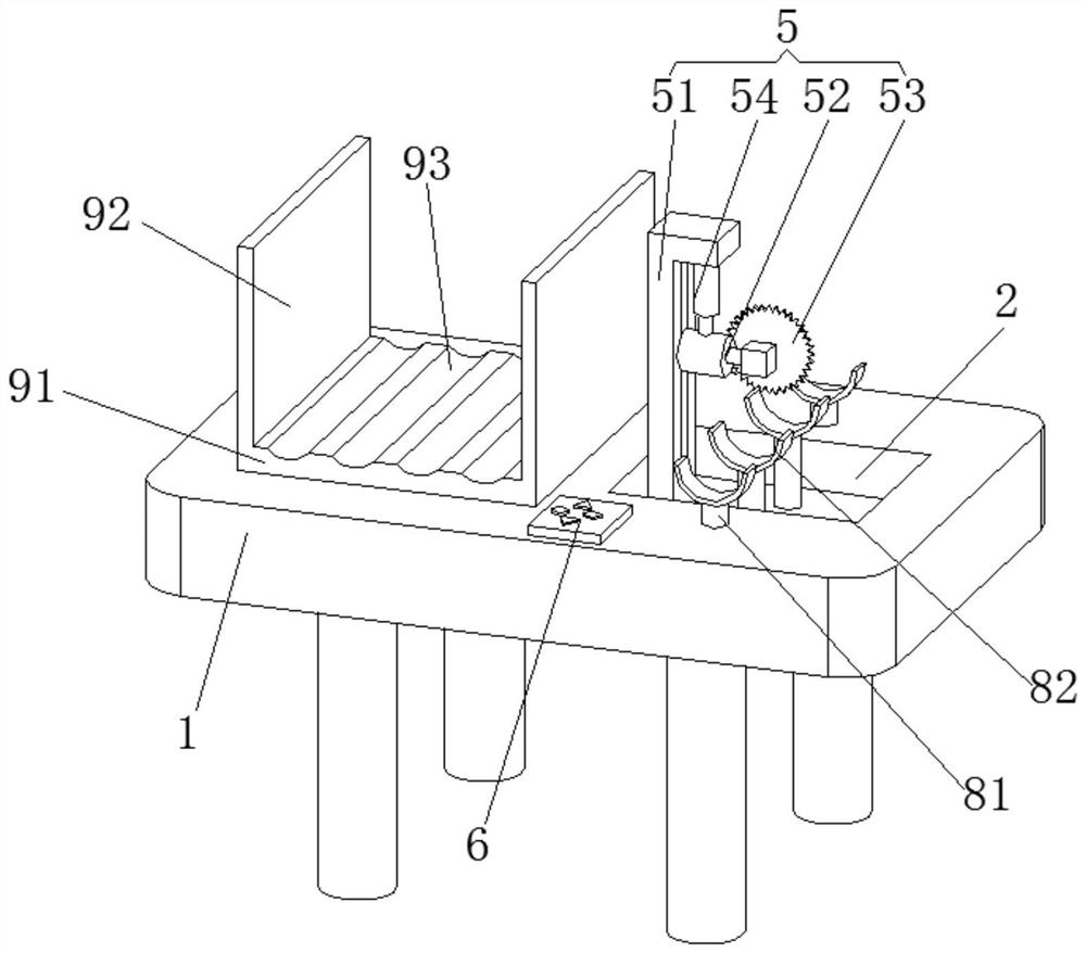
[0039] figure 1 A schematic structural view showing a pipe cutting device according to an embodiment of the present invention; figure 2 A schematic structural view of a pipe cutting device according to an embodiment of the present invention is shown (without a collection cover). Please refer to figure 1 with figure 2 , the present embodiment discloses a pipe cutting device, including an operation table 1 , a collection cover 3 , a cutting assembly 5 and a controller 6 . The top of the console 1 is provided with a collection tank 2 for collecting waste, and the collection cover 3 has a built-in accommodation chamber. The collection cover 3 is arranged on th...


PUM


Abstract

The invention relates to the field of cutting equipment, and discloses a pipe cutting device. The device comprises an operation table, a collecting cover, a cutting assembly and a controller. A collecting groove for collecting sweeps is formed in the top of the operation table, a containing cavity is arranged in the collecting cover, the collecting cover is arranged at the top of the collecting groove and covers the whole collecting groove, through holes for pipes to penetrate through are oppositely formed in the front side and the rear side of the collecting cover, and the cutting assembly isarranged in the containing cavity and used for cutting the pipes; and the controller is arranged on the operation table. According to the technical scheme, the invention provides the pipe cutting device. Through mutual cooperation of the collecting groove and the collecting cover, the sweeps generated during cutting completely fall into the collecting groove, the safety influence of splashing ofthe sweeps on operators in the cutting process is avoided, the cutting safety is improved, the sweeps are better collected, and recycling of the sweeps is facilitated.

Description

technical field [0001] The invention relates to the field of cutting equipment, in particular to a pipe material cutting device. Background technique [0002] Cutting machines are widely used in modern production. Many products need to use cutting machines in the process of processing. In many cases, cutting machines are used to cut pipes and other materials during the cutting process. It can still be used. At the same time, these waste chips are often small in size after cutting and other operations, making them easy to scatter in the air. Not only is it difficult to collect, but it is also more harmful to operators. Contents of the invention [0003] The object of the present invention is to provide a pipe material cutting device, which can well collect waste chips after cutting, prevent the waste chips from flying, and improve the safety of cutting. [0004] In order to achieve the above object, the present invention provides a pipe cutting device, comprising: [0005...

Claims


Application Information

Patent Timeline
Patent Type & Authority Applications(China)
IPC IPC(8): B23D21/00B23D19/00B23D33/02B23Q5/28B23Q11/00B23Q11/08
CPCB23D19/00B23D21/00B23D33/02B23Q5/28B23Q11/0042B23Q11/08
Inventor 张海汪莉化强
Owner ANHUI TSP ULTRA PRECISION MOLD
Why Eureka
Try Eureka