Annular laser cutting machine and using method

A laser cutting machine, laser machine technology, applied in laser welding equipment, welding equipment, metal processing equipment and other directions, can solve problems such as affecting workpiece assembly, affecting the safety of bypass wire workers, and unable to cut to a complete plane.

Pending Publication Date: 2020-12-01
佛山市富惟汽配有限公司
View PDF0 Cites 1 Cited by
  • Summary
  • Abstract
  • Description
  • Claims
  • Application Information

AI Technical Summary

Problems solved by technology

But this cutting method is started by the self-rotation of the workpiece
A large number of sparks will be generated when cutting the workpiece, which will affect the safety of bypass wires or workers, and when the self-rotation, the clamping force of the clamping workpiece is weakened, causing the cutting position of the workpiece to fluctuate up and down, and sometimes the complete cutting cannot be achieved Plane, which affects the assembly of later workpieces

Method used


Image

  • Annular laser cutting machine and using method
  • Annular laser cutting machine and using method
  • Annular laser cutting machine and using method

Examples


Embodiment Construction

[0034] Embodiments of the present invention are described in detail below, examples of which are shown in the drawings, wherein the same or similar reference numerals designate the same or similar elements or elements having the same or similar functions throughout. The embodiments described below by referring to the figures are exemplary only for explaining the present invention and should not be construed as limiting the present invention.

[0035] In describing the present invention, it should be understood that the terms "center", "longitudinal", "transverse", "length", "width", "thickness", "upper", "lower", "left", " The orientation or positional relationship indicated by "right", "vertical", "horizontal", "top", "bottom", "inner", "outer", "axial", "radial", "circumferential" is Based on the orientation or positional relationship shown in the drawings, it is only for the convenience of describing the present invention and simplifying the description, and does not indica...


PUM


Abstract

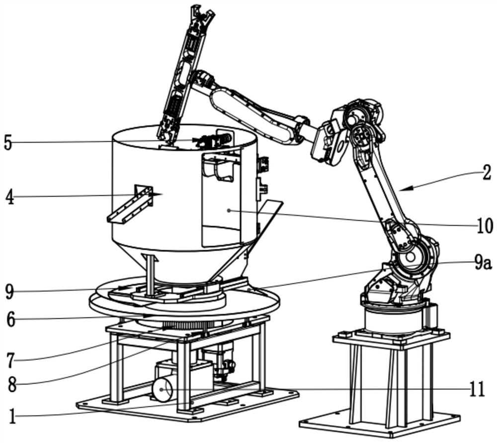
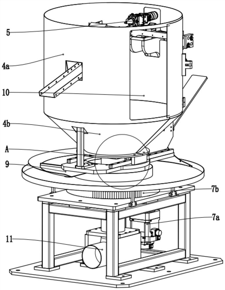
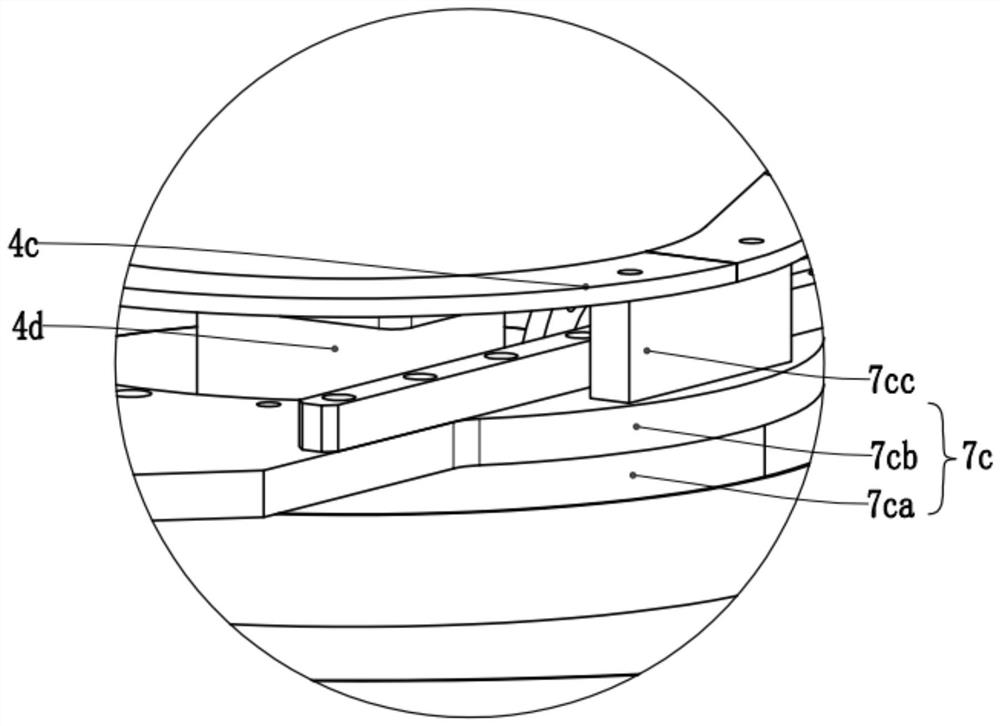
Provided is an annular laser cutting machine. The machine comprises a fixing frame, a clamping assembly, a fixing base, a cutting barrel, and an optical fiber wire spool. The optical fiber wire spoolis fixed above the fixing frame; the cutting barrel is arranged above the optical fiber wire spool; the fixing base is arranged inside the cutting barrel and used for clamping and fixing a workpiece;and the clamping assembly is arranged beside the fixing frame and used for clamping the workpiece to be placed on or away from the fixing base. A rotating assembly is arranged below the fixing frame,and a through hole for connecting the rotating assembly with the cutting barrel is formed in the middle of the optical fiber wire spool; the rotating assembly is in transmission connection with the cutting barrel; and the rotating assembly rotates to drive the cutting barrel to rotate. When the cutting barrel rotates, the fixing base keeps still, so that the fixing base keeps still during cutting,and the cutting barrel rotates to cut the workpiece, the clamping force on the workpiece cannot be weakened during cutting of the fixing base, and the workpiece is stably cut and the cutting openingof the workpiece is flat can be guaranteed.

Description

technical field [0001] The invention relates to the technical field of laser cutting, in particular to a ring laser cutting machine and a usage method. Background technique [0002] The current cutting machine clamps and fixes the workpiece, and a device for driving rotation is provided under the workpiece, and a laser device is arranged beside the workpiece to cut the workpiece. The rotating device drives the workpiece to rotate itself so that the workpiece is circularly cut by the laser device. However, this cutting method is started by the self-rotation of the workpiece. A large number of sparks will be generated when cutting the workpiece, which will affect the safety of bypass wires or workers, and when the self-rotation, the clamping force of the clamping workpiece is weakened, causing the cutting position of the workpiece to fluctuate up and down, and sometimes the complete cutting cannot be achieved. The plane affects the assembly of the workpiece in the later stage...

Claims


Application Information

Patent Timeline
IPC IPC(8): B23K26/38B23K26/08B23K26/142B23K26/70
CPCB23K26/0861B23K26/38B23K26/142B23K26/702
Inventor 徐丰
Owner 佛山市富惟汽配有限公司
Why Eureka
Try Eureka