Flange installation module and fire-fighting air duct production line with flange installation module

A flange and fire-fighting technology, used in sawing machine devices, metal sawing equipment, manufacturing tools, etc., can solve the problems of manual beating and curling, uneven quality, uneven quality, etc., to improve production efficiency, high product quality, and good seam. The effect of the edge effect

Active Publication Date: 2020-12-01
CHONGQING VOCATIONAL INST OF ENG
View PDF12 Cites 2 Cited by
  • Summary
  • Abstract
  • Description
  • Claims
  • Application Information

AI Technical Summary

Problems solved by technology

[0007] 1. Most of the fire-fighting ducts are made on-site, and the seams are hand-beaten, which is extremely inefficient, and the quality varies, making quality control very difficult
[0008] 2. Although the inventor has mentioned in the previous application (application number 2020105454699) that the flange can be fixed by crimping the flange, but it still involves manual beating on the crimping, and the problem still comes back to manual operation. The quality is even more uneven
[0009] At present, the main use of fully manual and semi-automatic processing methods seriously affects production efficiency and directly affects the competitiveness of enterprises. Therefore, it is imperative to adopt fully automated production technology.

Method used


Image

  • Flange installation module and fire-fighting air duct production line with flange installation module
  • Flange installation module and fire-fighting air duct production line with flange installation module
  • Flange installation module and fire-fighting air duct production line with flange installation module

Examples


Embodiment Construction

[0038] The following will clearly and completely describe the technical solutions in the embodiments of the present invention with reference to the drawings in the embodiments of the present invention.

[0039] In describing the present invention, it should be understood that the terms "upper", "lower", "front", "rear", "left", "right", "top", "bottom", "inner", " The orientation or positional relationship indicated by "outside", etc. is based on the orientation or positional relationship shown in the drawings, and is only for the convenience of describing the present invention and simplifying the description, rather than indicating or implying that the referred device or element must have a specific orientation, so as to Specific orientation configurations and operations, therefore, are not to be construed as limitations on the invention.

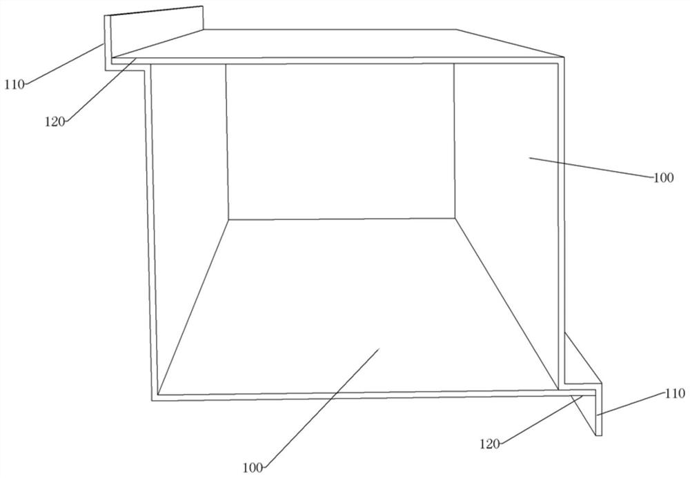
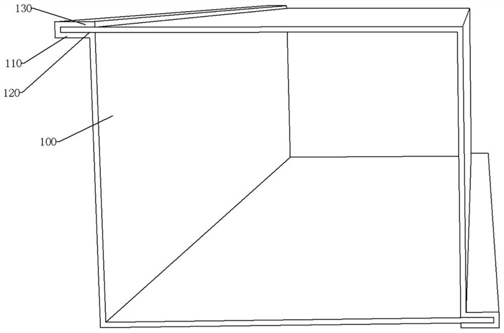
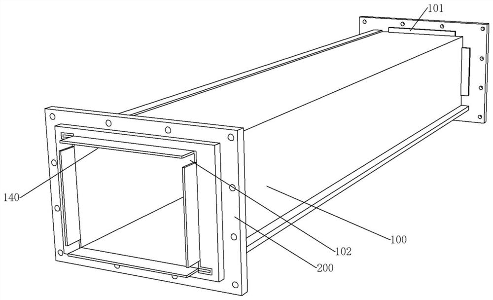
[0040] see Figure 1-Figure 4 , the present embodiment is used for processing the fire-fighting air duct, and the specific processing ste...


PUM


Abstract

The invention discloses a flange installation module and a fire-fighting air duct production line with the flange installation module. The fire-fighting air duct production line with the flange installation module comprises a platform module, a detection module, a grooving module, a conveying module, a flange sleeving module and the flange installation module. The platform module is used for splicing and sewing a fire-fighting air duct, wherein the spliced fire-fighting air duct is 100-1, and the hemmed fire-fighting air duct is 100-2. The detection module is used for detecting the flatness ofa sewn first hemming part. The grooving module is used for cutting bending grooves in the two ends of the fire-fighting air duct correspondingly, and a second hemming part without hemming is obtained. The conveying module is used for clamping the sewn fire-fighting air duct through a clamping mechanism and conveying the fire-fighting air duct. The flange sleeving module is used for taking out flanges from the interior of a storage side plate and then respectively enabling the flanges to sleeve the two ends of the fire-fighting air duct. The flange installation module is used for hemming the second hemming part without hemming towards a clamping part so that the second hemming part can clamp and fixe the flanges between flange bosses and the second hemming part. According to the flange installation module and the fire-fighting air duct production line, automatic sewing, detection, flange sleeving and flange fixing of the fire-fighting air duct can be realized.

Description

technical field [0001] The invention relates to the production technology of fire-fighting air ducts, in particular to a production line for fire-fighting air ducts. Background technique [0002] The current processing method of the fire smoke exhaust duct (referred to as the fire duct in this case) is roughly as follows: [0003] 1. Two bending plates are used to buckle each other to form a prototype; [0004] 2. Knock the seam portion 110 of the bent plate so that the seam portion 110 bends toward the clamping portion 120 to form the first curling portion 130, and the first curling portion 130 and the seam portion 110 clamp the clamping portion 120, thereby Realize the sewing of the whole fire duct; [0005] 3. Connect the flange 200, then drill holes on the flange and the fire-fighting air duct, and then tighten the screws to realize the flange 200 and install the flange on the fire-fighting air duct. [0006] This method mainly has the following defects: [0007] 1. ...

Claims


Application Information

Patent Timeline
Patent Type & Authority Applications(China)
IPC IPC(8): B23P19/04B23P19/00B21D39/00B21D39/02B21C51/00B23D49/00B23D51/00B23P15/00
CPCB21C51/00B21D39/00B21D39/02B23D49/00B23D51/00B23P15/00B23P19/001B23P19/04
Inventor 胡韶华罗元成蔡维汪女辉
Owner CHONGQING VOCATIONAL INST OF ENG
Why Eureka
Try Eureka