
Device and method for separating cover glass and display module from each other
A display module and cover glass technology, which is applied in the direction of manufacturing tools, hand-held tools, etc., can solve difficult problems and achieve the effect of speeding up disassembly
- Summary
- Abstract
- Description
- Claims
- Application Information
AI Technical Summary
Problems solved by technology
Method used
Image

Examples
Embodiment
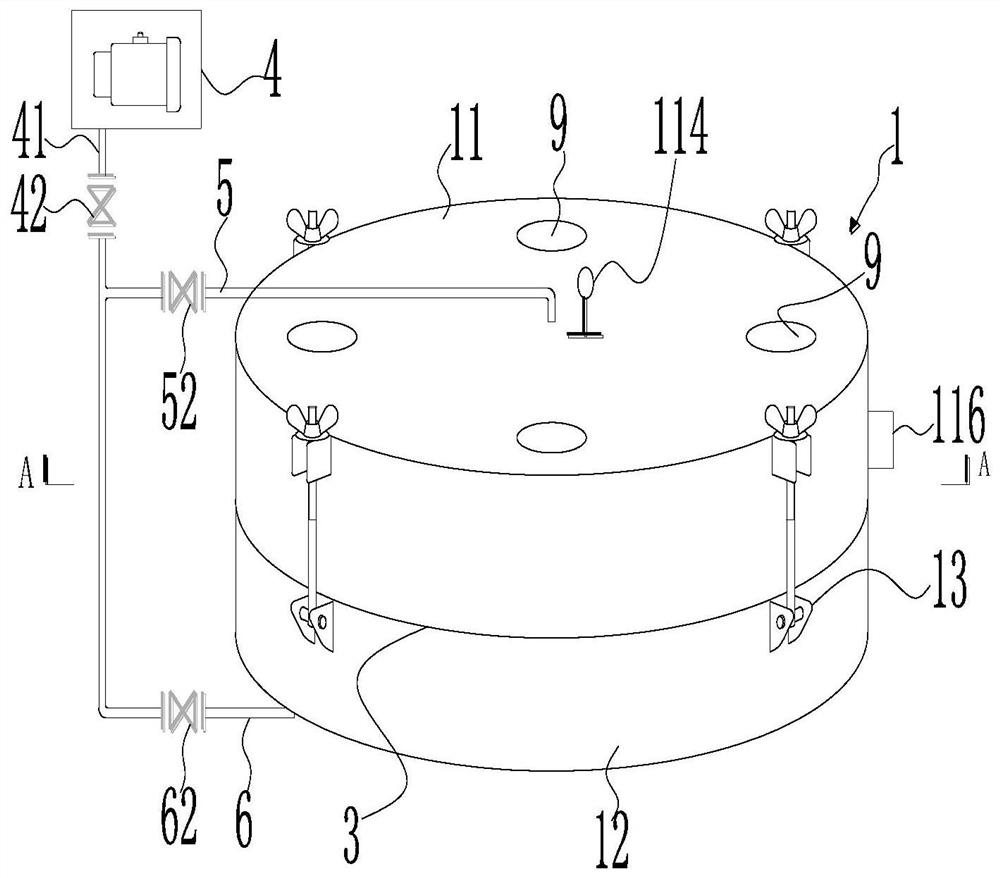
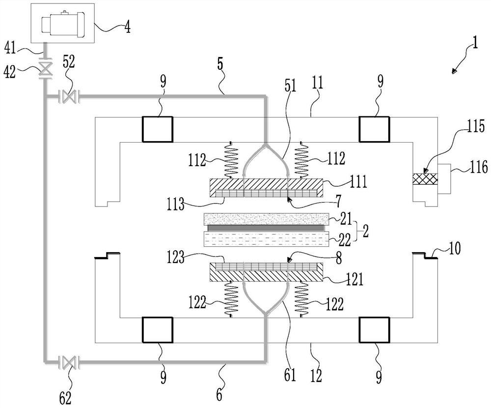
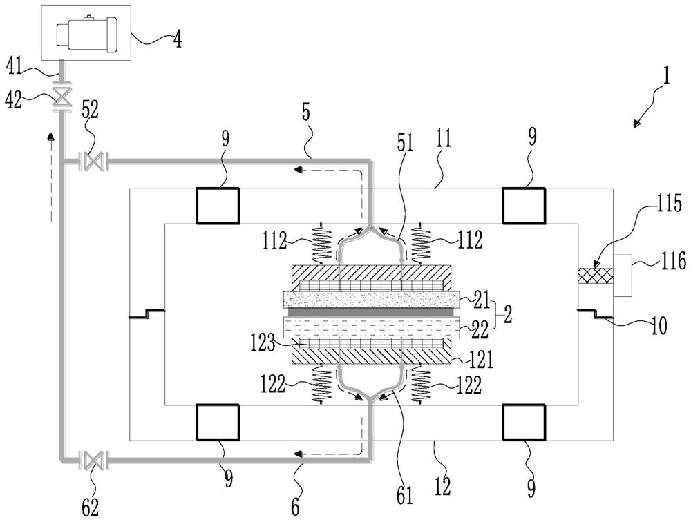
[0052] Such as figure 1 , figure 2 and image 3 As shown, the present invention is a device and method for separating the cover glass and the display module. The cover glass 21, the OCA glue and the display module 22 are placed in the airtight container 3, the first pressure vessel 11, the second pressure vessel 12 are coupled with each other through the locking device 13 to form a closed cavity 31. The display module 22 is placed on the second fixed plate 121. The first fixed plate 111 is on the side of the cover glass 21, and the second spring 112 and the second spring 122 secondly The component 2 to be disassembled is fixed between the first fixing plate 111 and the second fixing plate 121 , so as to be in close contact with each other. The first pressure vessel 11 and the second pressure vessel 12 are coupled to each other, and a closed space is formed in the airtight vessel 3 . Valve 116 is closed, no fluid is injected, and piston 9 is secured. Turn on the first heat...
PUM
 Abstract
Description
Claims
Application Information