Method for decomposing phenolic by-products

A technology for by-products and phenols, applied in the field of decomposing phenolic by-products, can solve problems such as discarding phenolic by-products

Active Publication Date: 2021-09-10
LG CHEM LTD
View PDF3 Cites 0 Cited by
  • Summary
  • Abstract
  • Description
  • Claims
  • Application Information

AI Technical Summary

Problems solved by technology

[0010] On the other hand, in the prior art, the phenolic by-products separated through the bottom of the phenol column are used as fuel or discarded without additional treatment

Method used


Image

  • Method for decomposing phenolic by-products
  • Method for decomposing phenolic by-products
  • Method for decomposing phenolic by-products

Examples


Embodiment 1

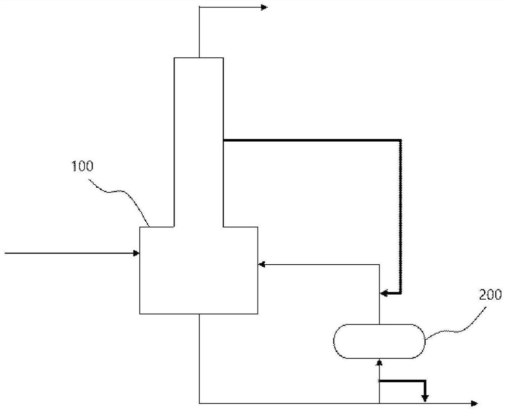
[0057] as figure 1As shown in the process flow diagram, the phenolic by-product stream of the composition shown in Table 1 is supplied to the decomposition device 100 at a flow rate of 1,000 kg / hr, and the phenolic by-product stream is thermally cracked. In this case, the working pressure of the decomposition device 100 was controlled to be normal pressure, and the working temperature of the decomposition device 100 was controlled to be 330°C. The active ingredient of the composition shown in Table 2 was recovered from the top discharge stream of the decomposition apparatus 100 . A part of the bottom discharge stream of the decomposition apparatus 100 is supplied to the reboiler 200 and the residual stream is discharged. In this case, the side discharge stream of the decomposition apparatus 100 was supplied to the reboiler 200 at a flow rate of 300 kg / hr to remove the pollutants accumulated in the reboiler 200 (solid line). The composition of the side discharge stream of the...

Embodiment 2

[0063] as figure 1 Referring to the process flow diagram shown, the phenolic by-product stream having the same composition as in Example 1 was supplied to the decomposition apparatus 100 at a flow rate of 1,000 kg / hr, and the phenolic by-product stream was thermally cracked. In this case, the operating pressure of the decomposition apparatus 100 was controlled to be normal pressure, and the operating temperature of the decomposition apparatus 100 was controlled to be 300°C. The active ingredient of the composition shown in Table 4 was recovered from the top discharge stream of the decomposition apparatus 100 . A part of the bottom discharge stream of the decomposition apparatus 100 is supplied to the reboiler 200 and the residual stream is discharged. In this case, the side discharge stream of the decomposition apparatus 100 was supplied to the reboiler 200 at a flow rate of 300 kg / hr to remove the pollutants accumulated in the reboiler 200 (solid line). The composition of t...

experiment example

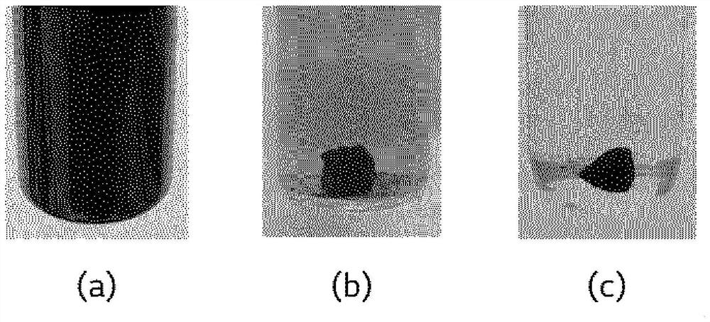
[0076] As pollutants accumulated in the reboiler 200, 5 g of tar with a high boiling point was immersed in a container containing 50 g of the side discharge stream of Example 1, a container containing 50 g of acetone of Comparative Example 1, and a container containing 50 g of the organic layer component of the APC BTM separator was placed in each of the containers, and each container was left for 7 hours, and the solubility of tar in each container was observed. The results are shown in image 3 middle. Specifically, in image 3 (a) shows a photograph showing a state in which 5 g of tar was immersed in a container containing 50 g of the side discharge stream of Example 1 and the container was left for 7 hours. image 3 (b) shows a photograph showing a state in which 5 g of tar was immersed in a container containing 50 g of acetone of Comparative Example 1 and the container was left for 7 hours. image 3 (c) shows a photograph showing a state in which 5 g of tar was immerse...


PUM


Abstract

The present invention relates to a method for decomposing phenolic by-products and, more specifically, provides a method for decomposing phenolic by-products, the method comprising the steps: supplying a phenolic by-product stream to a decomposing device to thermally decompose the stream (S10); recovering active ingredients from an upper discharge stream of the decomposing device and discharging high-boiling point materials from a lower discharge stream (S20); supplying a portion of the lower discharge stream of the decomposing device through a reboiler to the decomposing device, and discharging the remainder of the stream (S30); and supplying a side discharge stream of the decomposing device to the reboiler (S40).

Description

[0001] Cross References to Related Applications [0002] This application claims the benefit of priority from Korean Patent Application No. 10-2019-0113589 filed on September 16, 2019, the entire contents of which are incorporated herein by reference. technical field [0003] The present invention relates to a method for decomposing phenolic by-products, and more particularly, to a method for removing pollutants accumulated in a reboiler when decomposing phenolic by-products generated in a phenol production process. Background technique [0004] Typically, about 95% of the phenol used in the world is produced by the Hock process. The Hawke process is performed in three steps: step (1), formation of cumene by alkylation of benzene with propylene; step (2), oxidation of cumene to peroxide by combining cumene with oxygen cumene hydroperoxide (CHP); and step (3): decomposing cumene hydroperoxide into phenol and acetone by an acid decomposition reaction in the presence of an aci...

Claims


Application Information

Patent Timeline
Patent Type & Authority Applications(China)
IPC IPC(8): C07C37/52C07C39/04C07C45/51C07C49/78
CPCC07C37/52C07C45/51C07C39/04C07C49/78C07C1/20C07C4/24C07C45/82C07C15/085C07C15/44B01D53/005C07C37/74B01D17/02B01D2257/70C07C7/04
Inventor 姜旻皙李相范张致贤
Owner LG CHEM LTD
Why Eureka
Try Eureka