
Device and method for reducing effects of video artifacts

a technology of video artifacts and devices, applied in the field of devices and methods for reducing the effects of video artifacts, can solve the problems of loss of video image portions and appearance of thin lines, and achieve the effect of reducing the noise conten

Active Publication Date: 2007-12-06
PSIP LLC
View PDF101 Cites 127 Cited by
  • Summary
  • Abstract
  • Description
  • Claims
  • Application Information

AI Technical Summary

Benefits of technology

The system effectively reduces the size and position of video artifacts, enhancing image quality and reducing procedural discomfort by ensuring synchronized imaging and illumination.

Problems solved by technology

This may cause loss of portions of the video image and appearance of a “thin line” in the video image.

Method used


Image

  • Device and method for reducing effects of video artifacts
  • Device and method for reducing effects of video artifacts
  • Device and method for reducing effects of video artifacts

Examples


Embodiment Construction

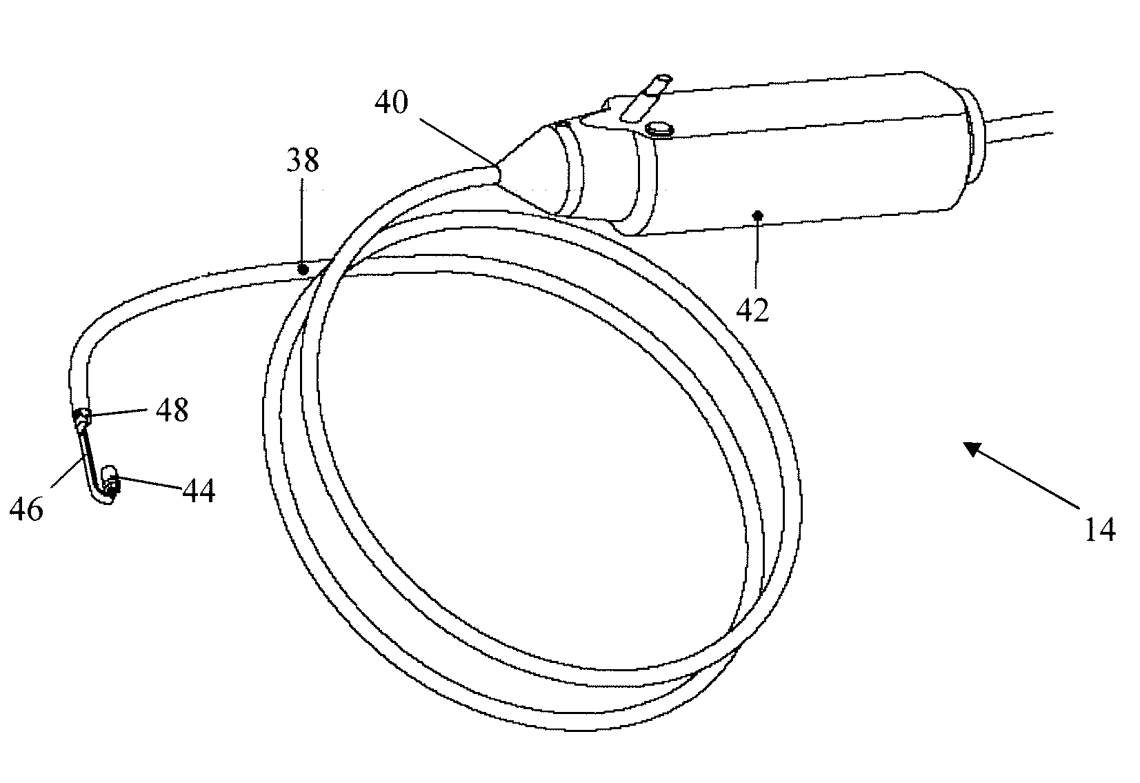
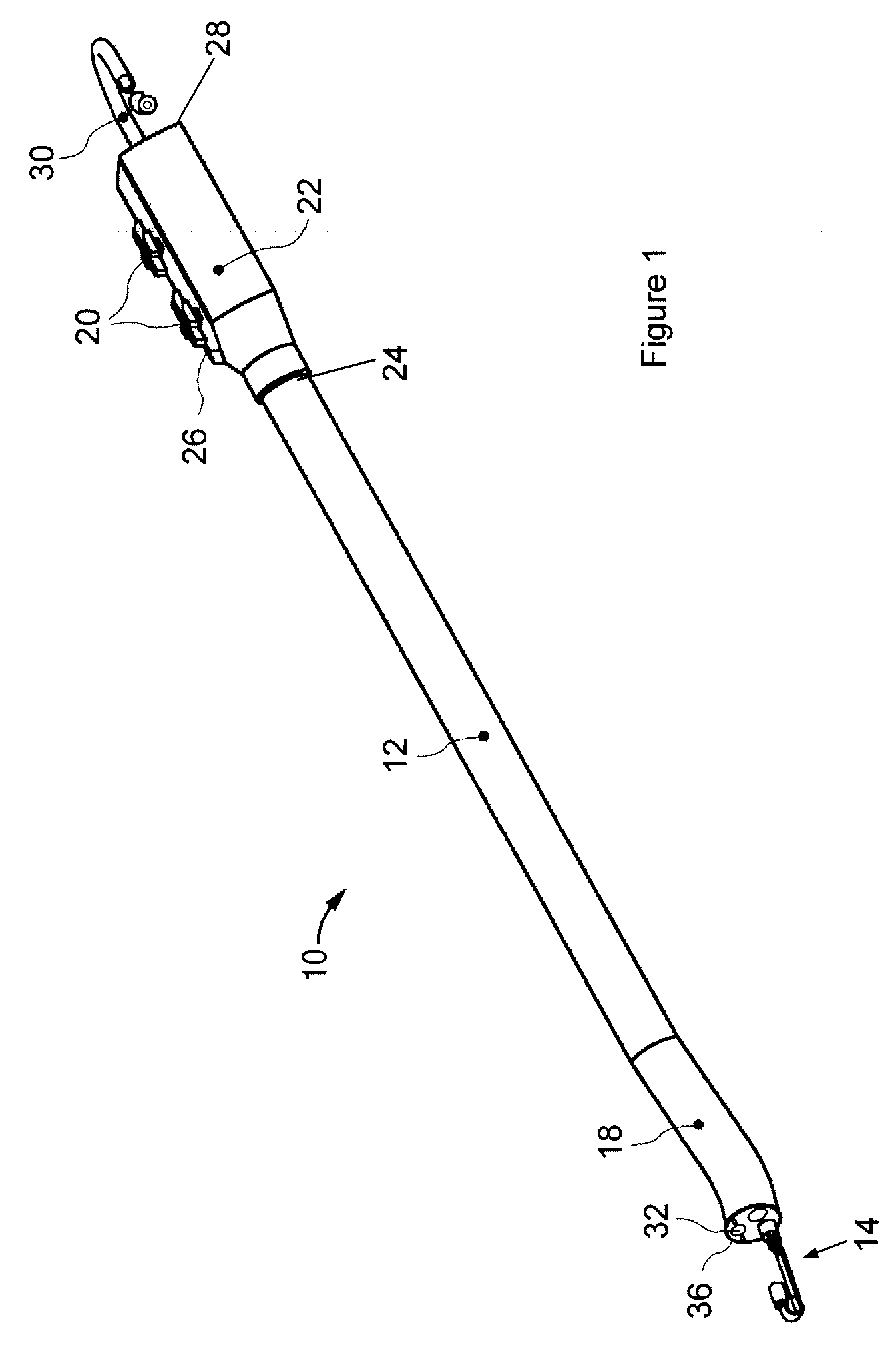
[0039]FIG. 1 illustrates an exemplary endoscope 10 of the present invention. This endoscope 10 can be used in a variety of medical procedures in which imaging of a body tissue, organ, cavity or lumen is required. The types of procedures include, for example, anoscopy, arthroscopy, bronchoscopy, colonoscopy, cystoscopy, EGD, laparoscopy, and sigmoidoscopy.

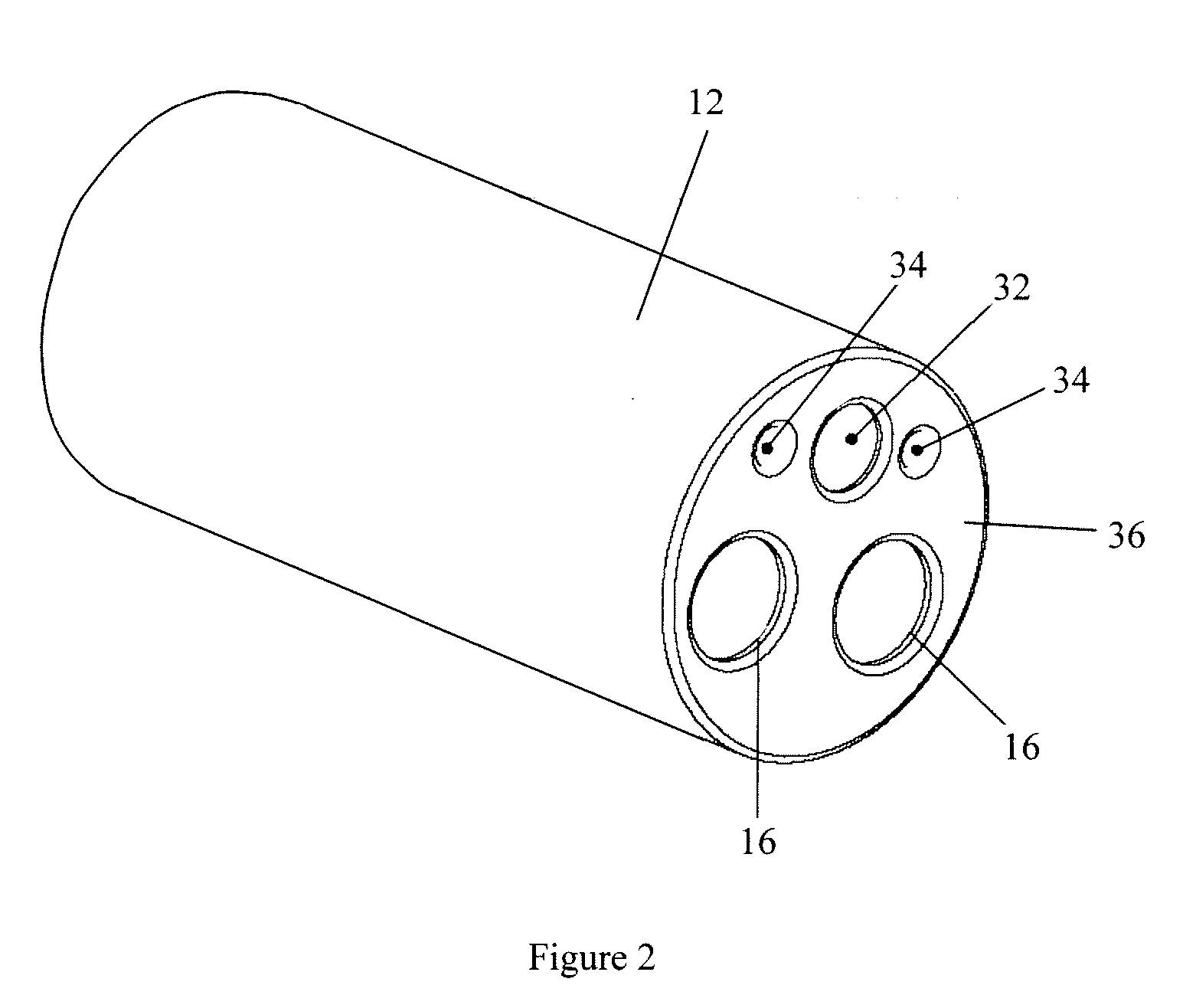
[0040] The endoscope 10 of FIG. 1 includes an insertion tube 12 and an imaging assembly 14, a section of which is housed inside the insertion tube 12. As shown in FIG. 2, the insertion tube 12 has two longitudinal channels 16. In general, however, the insertion tube 12 may have any number of longitudinal channels. An instrument can reach the body cavity through one of the channels 16 to perform any desired procedures, such as to take samples of suspicious tissues or to perform other surgical procedures such as polypectomy. The instruments may be, for example, a retractable needle for drug injection, hydraulically actuated scissors,...


PUM


Abstract

A method for reducing an effect of a video artifact includes adjusting a phase of a second imaging device's video clock signal so that a phase of the second imaging device's video synchronization signal matches a phase of a first imaging device's video synchronization signal. An endoscopic system includes a first imaging device, a second imaging device, a light source, and a controller that reduces an artifact in an image produced by the first imaging device. In some embodiments, the first imaging device faces the light source.

Description

[0001] This application claims the benefit of U.S. Provisional Patent Application No. 60 / 801,748, filed May 19, 2006, the entire disclosure of which is incorporated herein by reference.TECHNICAL FIELD OF THE INVENTION [0002] The present invention relates to a device and method for reducing effects of video artifacts. BACKGROUND OF THE INVENTION [0003] Multiple endoscopic devices with multiple cameras and light sources may be used for medical procedures, inspection of small pipes, or remote monitoring. For example, such an endoscopic device may be a medical endoscope comprising a flexible tube, and a camera and a light source mounted on the distal end of the flexible tube. The endoscope is insertable into an internal body cavity through a body orifice to examine the body cavity and tissues for diagnosis. The tube of the endoscope has one or more longitudinal channels, through which an instrument can reach the body cavity to take samples of suspicious tissues or to perform other surgi...

Claims


Application Information

Patent Timeline
Patent Type & Authority Applications(United States)
IPC IPC(8): H04N7/18
CPCA61B1/0005A61B1/00181A61B1/0051A61B1/0125A61B1/05A61B1/045A61B1/00179A61B1/00006A61B1/00009A61B1/005A61B1/0676G02B23/2423A61B1/0625A61B1/0655A61B1/000094
Inventor BAYER, LEXROBERT, OKAS
Owner PSIP LLC
Learn More