
Rear skirt connection type thrust transmission device for engine ignition test of solid rocket

A technology of solid rockets and delivery devices, which is applied to rocket motor devices, machines/engines, jet propulsion devices, etc., can solve problems such as high difficulty in implementation, low efficiency, and complicated methods, so as to improve test efficiency, reduce test costs, and improve safety effect

Active Publication Date: 2020-12-01
XIAN AEROSPACE PROPULSION TESTING TECH RES INST
View PDF7 Cites 6 Cited by
  • Summary
  • Abstract
  • Description
  • Claims
  • Application Information

AI Technical Summary

Problems solved by technology

[0005] Considering that in the existing ground ignition experiments of solid rocket motors, the rear skirt connection horizontal test method is relatively complicated, inefficient and difficult to implement, the present invention proposes a thrust transfer device for solid rocket motor ignition tests in the form of rear skirt connection, wherein The connection with the rear skirt of the engine adopts the form of upper and lower splits, and the horizontal installation of the engine can be quickly realized without the use of squirrel cages and overturning tooling; the arc seat is designed as an adjustable one integrated with the device, and can be directly supported by adjusting the height The engine avoids the stress concentration at the connection position of the rear skirt caused by the self-weight of the engine; the detachable thrust rod and the ring also facilitate the test, ensure the precise installation of the engine, and avoid the occurrence of interference. The dynamic fixed frame connection can meet the test requirements of engines of different specifications

Method used


Image

  • Rear skirt connection type thrust transmission device for engine ignition test of solid rocket
  • Rear skirt connection type thrust transmission device for engine ignition test of solid rocket
  • Rear skirt connection type thrust transmission device for engine ignition test of solid rocket

Examples


Embodiment Construction

[0041] Embodiments of the present invention are described in detail below, and the embodiments are exemplary and intended to explain the present invention, but should not be construed as limiting the present invention.

[0042] In describing the present invention, it should be understood that the terms "center", "longitudinal", "transverse", "length", "width", "thickness", "upper", "lower", "front", " Orientation indicated by rear, left, right, vertical, horizontal, top, bottom, inside, outside, clockwise, counterclockwise, etc. The positional relationship is based on the orientation or positional relationship shown in the drawings, which is only for the convenience of describing the present invention and simplifying the description, rather than indicating or implying that the referred device or element must have a specific orientation, be constructed and operated in a specific orientation, Therefore, it should not be construed as limiting the invention.

[0043]The invention...


PUM


Abstract

The invention provides a rear skirt connection type thrust transmission device for engine ignition test of a solid rocket. The thrust transmission device comprises a front end connecting plate, a base, a rear skirt connecting plate, an arc-shaped seat, a connecting rod and a holding ring; the rear skirt connecting plate adopts an up-and-down split form, so that horizontal installation of an enginecan be quickly realized without the help of a mouse cage or an overturning tool; and the arc-shaped seat is designed into a height-adjustable type and is integrated with the device. The engine is directly supported by adjusting the height, and stress concentration at the connecting position of a rear skirt caused by the dead weight of the engine is avoided; and a detachable thrust connecting rodand the holding ring also facilitate the test, ensure the accurate installation of the engine, avoid the occurrence of interference, and can be connected with different movable and fixed frames to meet the test requirements of engines of different specifications. The device has the advantages of being easy and convenient to use, low in cost, high in efficiency, good in safety and the like.

Description

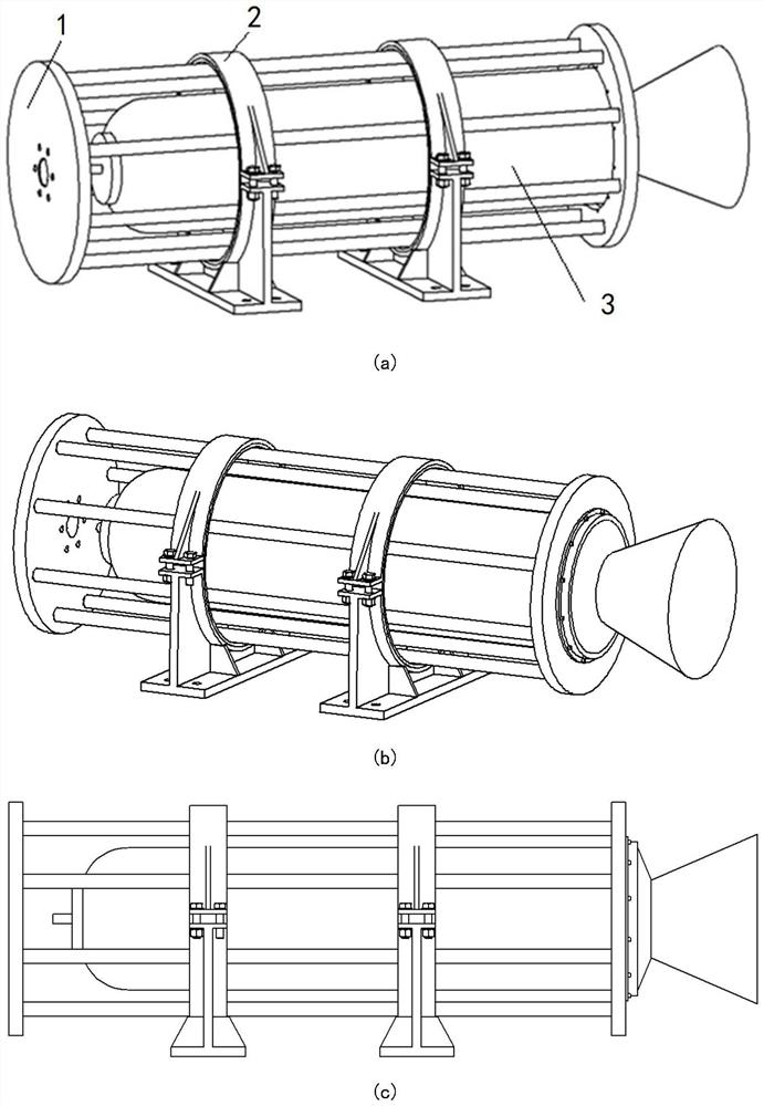
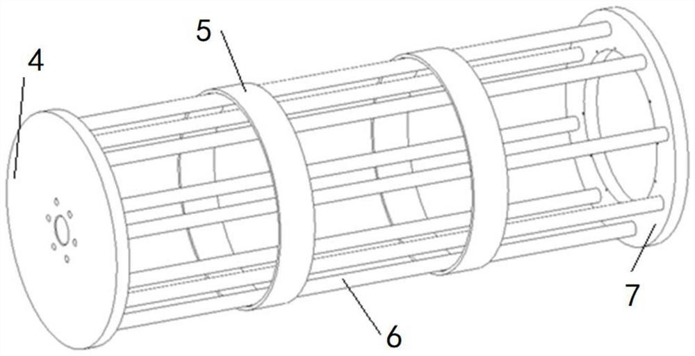
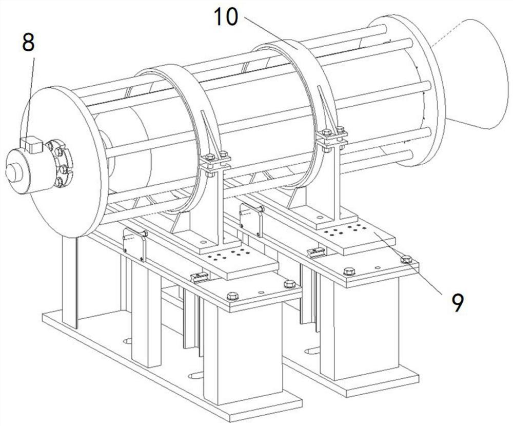
technical field [0001] The invention relates to the technical field of ignition tests of solid rocket motors, in particular to a thrust transmission device for ignition tests of solid rocket motors in the form of rear skirt connection. Background technique [0002] The solid rocket motor ground ignition test is a key test that directly affects the model development and product performance. The traditional solid rocket motor ground ignition test mostly adopts the test form in which the front skirt of the solid rocket motor is connected to the transition frame and then connected to the sensor, and the motor is supported on the arc seat. For some specially designed solid rocket motors, only the rear skirt connection is provided, and the squirrel-cage thrust frame is generally used in the existing schemes for ground tests, such as Figure 1 to Figure 3 shown. The currently used squirrel-cage test device is mainly composed of a squirrel-cage thrust frame and a pair of arc-shaped...

Claims


Application Information

Patent Timeline
Patent Type & Authority Applications(China)
IPC IPC(8): F02K9/96F02K9/95
CPCF02K9/96F02K9/95F02K9/08F05D2260/83
Inventor 刘畅王哲宋飞飞李贤君祝子文高永刚朱瑶崔宇杰孙剑虹
Owner XIAN AEROSPACE PROPULSION TESTING TECH RES INST
Learn More