Gas pressure regulating cabinet intelligent system and method

A gas pressure regulating and pressure regulating cabinet technology, which is applied in pipeline systems, gas/liquid distribution and storage, mechanical equipment, etc. It can solve the problems of gas outage, high possibility of accidents, long time, etc., and achieve stable and reliable Good performance, reduced possibility, effect of structural protection

Pending Publication Date: 2020-12-01
襄阳山城燃气设备科技有限公司
View PDF1 Cites 3 Cited by
  • Summary
  • Abstract
  • Description
  • Claims
  • Application Information

AI Technical Summary

Problems solved by technology

[0008] Aiming at the above-mentioned deficiencies existing in the prior art, the present invention provides an intelligent method and system for a gas pressure regulating cabinet to solve the problem that the acquisition and analysis of real-time data cannot be realized at present; the real-time control of equipment cannot be realized, and accidents occur The possibility is high; it is impossible to timely warn and deal with accidents such as air leakage and abnormal air pressure, which may lead to problems such as long-term gas stop phenomenon

Method used


Image

  • Gas pressure regulating cabinet intelligent system and method
  • Gas pressure regulating cabinet intelligent system and method
  • Gas pressure regulating cabinet intelligent system and method

Examples


Embodiment 1

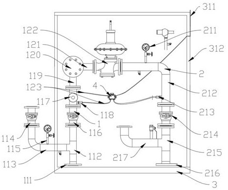
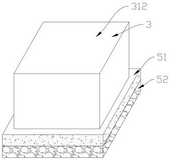
[0033] like Figure 1-4 As shown in the figure, the intelligent system of the gas pressure regulating cabinet includes a control module box 4, an air intake assembly 1, an air outlet assembly 2 and a box assembly 3. The air intake assembly 1 and the air outlet assembly 2 are connected by pipes, and the air intake assembly 1 is connected to the air outlet assembly. The components 2 are all fixedly connected to the inner lower surface of the box body component 3, and the control module box 4 is connected to the air intake component 1 and the air outlet component 2 through cables;

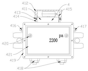
[0034] The control module box 4 includes a battery valve line connector 416, an antenna connector 417, two avionics plugs 418 and a housing 419. Both sides of the housing 419 are fixedly connected to the battery valve line connector 416 and the antenna connector 417 respectively. The avionics plug 418, the two avionics plugs 418 are fixedly connected with the housing 419. The battery valve line conne...

Embodiment 2

[0041] This embodiment is a further improvement of the previous embodiment, such as Figure 1-4 As shown in the figure, the intelligent system of the gas pressure regulating cabinet includes a control module box 4, an air intake assembly 1, an air outlet assembly 2 and a box assembly 3. The air intake assembly 1 and the air outlet assembly 2 are connected by pipes, and the air intake assembly 1 is connected to the air outlet assembly. The components 2 are all fixedly connected to the inner lower surface of the box body component 3, and the control module box 4 is connected to the air intake component 1 and the air outlet component 2 through cables;

[0042] The control module box 4 includes a battery valve line connector 416, an antenna connector 417, two avionics plugs 418 and a housing 419. Both sides of the housing 419 are fixedly connected to the battery valve line connector 416 and the antenna connector 417 respectively. The avionics plug 418, the two avionics plugs 418 a...


PUM


Abstract

The invention belongs to the technical field of gas pressure regulation, and particularly relates to a gas pressure regulating cabinet intelligent system and a method. The system comprises a control module box, an air inlet assembly, an air outlet assembly and a box body assembly, the air inlet assembly is connected with the air outlet assembly through a pipeline, the air inlet assembly and the air outlet assembly are fixedly connected to the lower surface of the interior of the box body assembly, and the control module box is connected with the air inlet assembly and the air outlet assembly through cables. The control module box comprises a battery valve line connector, an antenna connector, two avionics plugs and a shell. Two sides of the shell are fixedly connected with the battery valve line connector and the antenna connector respectively. The invention further discloses a use method of the gas pressure regulating cabinet intelligent system. The use method comprises the steps of equipment installation, software installation, software operation and the like. According to the system and method, the problems that real-time data acquisition and analysis cannot be realized in the prior art, real-time control of equipment cannot be realized, and accidents such as air leakage and abnormal air pressure cannot be warned and handled in time are solved.

Description

technical field [0001] The invention belongs to the technical field of gas pressure regulation, and in particular relates to an intelligent method and system for a gas pressure regulation cabinet. Background technique [0002] Existing gas pressure regulating cabinets only rely on manual on-site control, recording and collecting data. If the equipment fails, it is often not detected in time, resulting in gas shutdown. The operating data parameters cannot be reported in time and are often missed. The reason is that the existing communication scheme can only transmit data wirelessly and cannot be controlled remotely. [0003] The Chinese patent with publication number CN107782400A discloses a gas pressure regulating and measuring cabinet, which includes a cabinet body, a membrane gas meter located in the cabinet, an intake pipe connected to the intake end of the membrane gas meter, and a gas outlet of the membrane gas meter. A temperature sensor for measuring the temperature...

Claims


Application Information

Patent Timeline
Patent Type & Authority Applications(China)
IPC IPC(8): F17D3/01F17D5/00
CPCF17D3/01F17D5/005
Inventor 王方阳邱云袁青松毛育文钟传继
Owner 襄阳山城燃气设备科技有限公司
Why Eureka
Try Eureka