Wafer drying method

A drying method and wafer technology, applied in electrical components, semiconductor/solid-state device manufacturing, circuits, etc., can solve problems such as uneven drying of the wafer surface, achieve the effect of improving drying uniformity and avoiding particle agglomeration

Pending Publication Date: 2020-12-01
BEIJING NAURA MICROELECTRONICS EQUIP CO LTD
View PDF0 Cites 0 Cited by
  • Summary
  • Abstract
  • Description
  • Claims
  • Application Information

AI Technical Summary

Problems solved by technology

[0009] The present invention aims to solve at least one of the technical problems in the prior art, and proposes a wafer drying method to solve the phenomenon of uneven drying of the wafer surface in the prior art

Method used


Image

  • Wafer drying method
  • Wafer drying method

Examples


Embodiment Construction

[0035] In order to enable those skilled in the art to better understand the technical solution of the present invention, the wafer drying method provided by the present invention will be described in detail below in conjunction with the accompanying drawings.

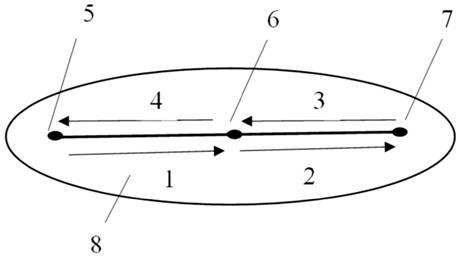
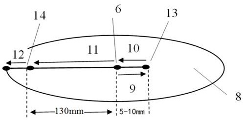
[0036] The wafer drying method provided by the present invention includes moving the shower head according to a preset path, and selectively opening the shower head in at least a section of the preset path to spray dry gas to the surface of the rotating wafer; at the same time, according to the shower head The variation of the horizontal spacing between the center of the wafer and the center of the wafer adjusts the speed at which the shower head moves so that the drying speed on the wafer surface tends to be consistent. Wherein, the so-called horizontal distance refers to the radial distance between the point where the center of the showerhead is vertically projected on the wafer surface and the center of the wafer. In...


PUM


Abstract

The invention provides a wafer drying method, which comprises the following steps of: selecting at least one path from the whole preset moving path of a spray head to open the spray head so as to spray dry gas to the surface of a rotating wafer, and adjusting the moving speed of the spray head according to the change of a horizontal distance between the spray head and the center of the wafer. Thus, the opening distance and the moving speed of the spray head can be flexibly adjusted according to the difference between the linear speed and the centrifugal force of each position on the surface ofthe wafer, so that the drying speed of each position on the surface of the wafer tends to be consistent, the drying uniformity can be further improved, and the phenomenon of annular particle agglomeration on the surface of the wafer is avoided.

Description

technical field [0001] The invention relates to the field of semiconductor manufacturing, in particular to a wafer drying method. Background technique [0002] In the cleaning process of semiconductor wafers, drying the wafer surface is a very important part. Because after the cleaning process is finished, a small amount of liquid (usually water) will remain on the surface of the wafer. If the drying is not sufficient, defects such as "water marks" will be formed on the surface of the wafer, so the drying effect directly affects the quality of the wafer. Product yield performance on a round surface. [0003] The current drying process is mainly to use the nozzle to swing back and forth above the wafer at a constant speed several times and spray the drying gas during the high-speed rotation of the wafer to achieve the purpose of drying. see figure 1 The moving trajectory of the shown prior art nozzle, the specific process is as follows: [0004] 1. The nozzle moves from t...

Claims


Application Information

Patent Timeline
Patent Type & Authority Applications(China)
IPC IPC(8): H01L21/02H01L21/67
CPCH01L21/02041H01L21/67034
Inventor 刘效岩
Owner BEIJING NAURA MICROELECTRONICS EQUIP CO LTD
Why Eureka
Try Eureka