Forest firefighting fire extinguishing device capable of enhancing stability based on electromagnetic force
A fire extinguishing device and a stable technology, which is applied in the field of forest fire extinguishing devices, can solve the problems of increasing safety, the inability of fire extinguishing equipment to continuously extinguish fires, and a large range of access, so as to increase safety, reduce occupied space, and increase adaptability Effect
- Summary
- Abstract
- Description
- Claims
- Application Information
AI Technical Summary
Problems solved by technology
Method used
Image
Examples
Embodiment 1
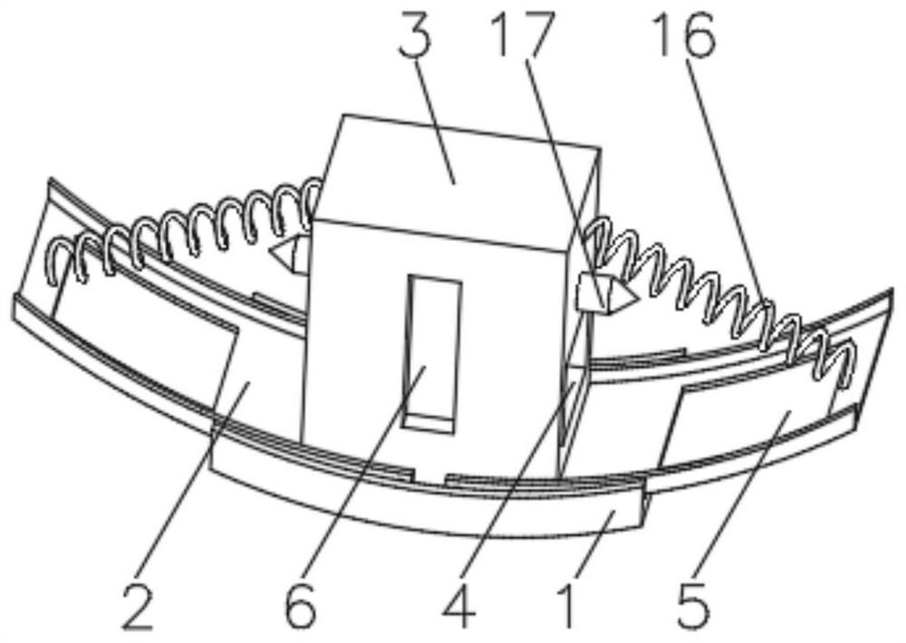
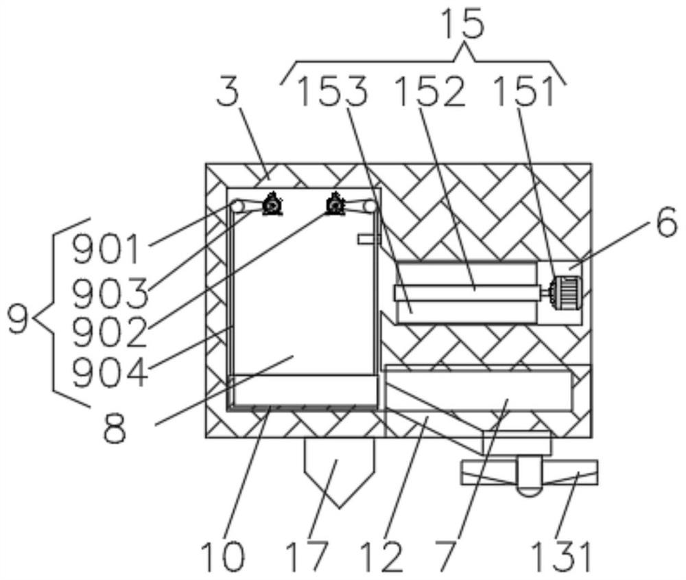
[0028] see Figure 1-5, the present invention provides a technical solution: a forest fire extinguishing device based on electromagnetic force enhanced stability, including a base plate 1, a walking plate 2 is symmetrically installed on the top of the base plate 1, the walking plate 2 is rotationally connected with the base plate 1, and the walking plate 2 The top of the fire extinguishing box 3 is rotatably connected with a fire extinguishing box 3, and the two sides of the fire extinguishing box 3 are symmetrically provided with a soil borrowing trough 4, and the top of the walking board 2 is provided with a soil borrowing port 5 that is compatible with the soil borrowing trough 4, and one side of the fire extinguishing box 3 The middle position is provided with a soil injection port 6, and the soil collecting tank 4 is symmetrically provided with a soil collecting tank 7 on both sides of the inner wall of the soil borrowing tank 4, and a lift tank 8 is provided inside the fi...
Embodiment 2
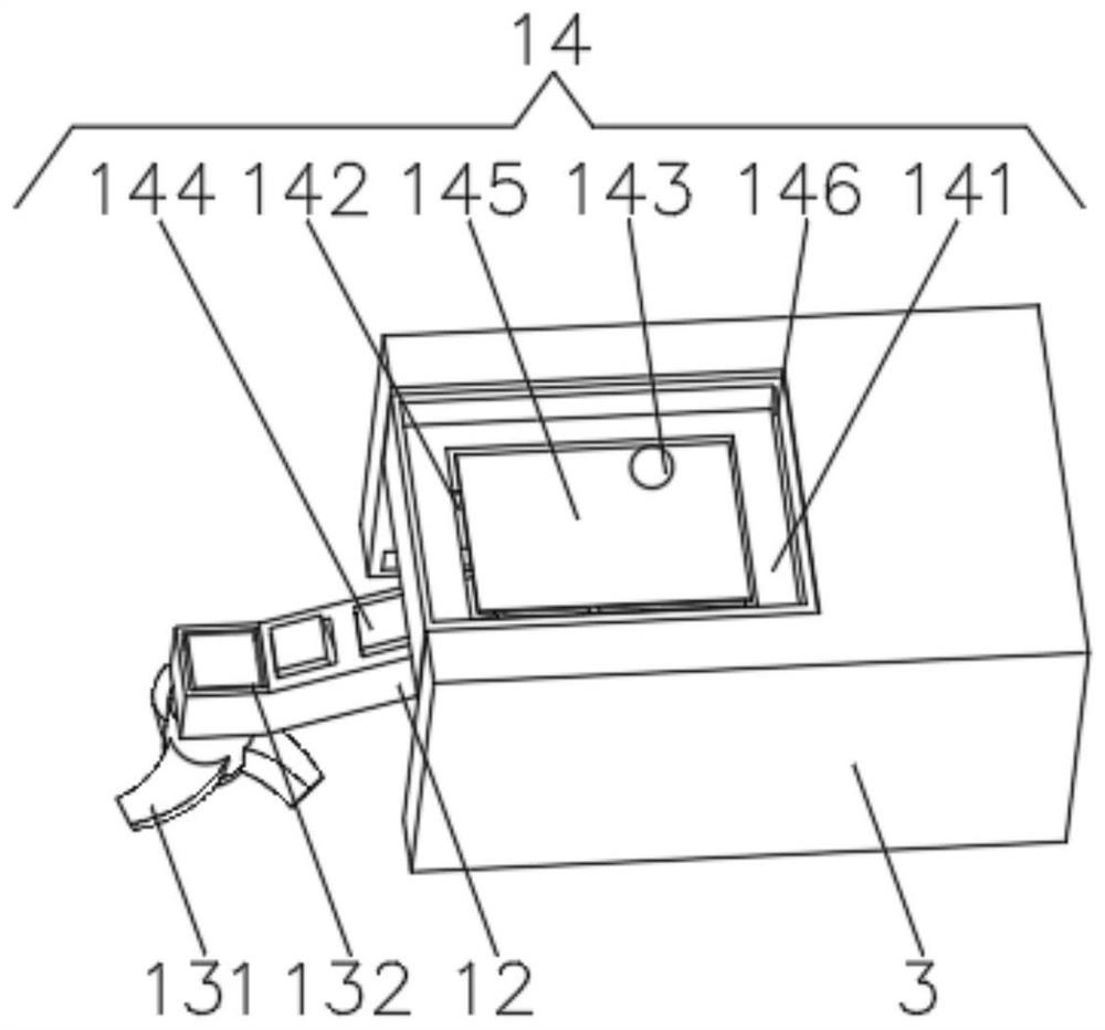
[0035] see Figure 1-5 , the present invention provides a technical solution: on the basis of Embodiment 1, an electromagnetic balance device 14 is installed on the inner wall of the soil borrowing tank 4, and the electromagnetic balancing device 14 includes a mounting frame 141, and the mounting frame 141 is installed on the inner wall of the soil borrowing tank 4 Positioned above the extension plate 11, the bottom of the installation frame 141 is evenly installed with an electromagnet 142, the top of the installation frame 141 is slidably connected with a rolling ball 143, and the top of the installation frame 141 is installed with a switch corresponding to the electromagnet 142, and the rotating plate The top of 12 is uniformly equipped with a magnet block 144, and the magnet block 144 is the same as the end magnetic pole close to the electromagnet 142.
[0036] A smooth plate 145 is fixedly connected between inner walls of the installation frame 141 , and a limit frame 146...
Embodiment 3
[0039] see Figure 1-5 , the present invention provides a technical solution: on the basis of Embodiment 1, an extension groove 111 is opened on the top of the extension plate 11, and an extension block 113 is fixedly connected to one side of the inner wall of the extension groove 111 through an extension spring 112, and the extension block 113 The top is fixedly connected with a rotating shaft 114 , and the end of the rotating shaft 114 away from the extension block 113 passes through the rotating plate 12 and is rotatably connected with the rotating plate 12 .
[0040] During use, the rotary plate 12 is turned over until the soil rotary knife 131 contacts the ground and the soil rotary is started. When rotating downwards to the below of the soil-borrowing mouth 5, the extension spring 112 promotes the rotating plate 12 to move to the outside of the soil-borrowing mouth 5 and continue to rotate to get soil.
PUM
 Abstract
Description
Claims
Application Information
 - R&D
- Intellectual Property
- Life Sciences
- Materials
- Tech Scout
- Unparalleled Data Quality
- Higher Quality Content
- 60% Fewer Hallucinations
Browse by: Latest US Patents, China's latest patents, Technical Efficacy Thesaurus, Application Domain, Technology Topic, Popular Technical Reports.
© 2025 PatSnap. All rights reserved.Legal|Privacy policy|Modern Slavery Act Transparency Statement|Sitemap|About US| Contact US: help@patsnap.com


