
Thin-wall flat-bottom blanking cap with weakening groove and forming mold and method thereof

A forming method and technology for weakening grooves, which are applied in forming tools, manufacturing tools, jet propulsion devices, etc., can solve the problems of high processing cost, inability to meet design requirements, and large processing deformation.

Inactive Publication Date: 2020-12-04
XIAN AEROSPACEMOTOR MACHINE FACTORY
View PDF14 Cites 4 Cited by
  • Summary
  • Abstract
  • Description
  • Claims
  • Application Information

AI Technical Summary

Problems solved by technology

Aluminum rods for mechanical processing are used, and the utilization rate of raw materials is only 7%. In addition, due to the large deformation of the material processing, it needs to go through many times of natural aging and artificial aging, the processing cycle is long, and the processing cost is high.
[0004] The traditional way of opening the blocking cap is to open and release the pressure from the bonding surface of the opening of the blocking cap to the rupture. For the blocking cap with weakened groove, a certain depth of weakening groove is designed on the bottom surface of the blocking cap, and the pressure reaches the design value during operation. When splitting from the center in the form of petals to release pressure, there is no thrown object in the working process, but the existing process method is difficult to realize; and the general spinning forming method cannot meet the special requirements of the design requirements, which are thin in the middle and high in thickness on both sides.

Method used


Image

  • Thin-wall flat-bottom blanking cap with weakening groove and forming mold and method thereof
  • Thin-wall flat-bottom blanking cap with weakening groove and forming mold and method thereof
  • Thin-wall flat-bottom blanking cap with weakening groove and forming mold and method thereof

Examples


Embodiment Construction

[0042] The embodiments described below by referring to the figures are exemplary and are intended to explain the present invention and should not be construed as limiting the present invention.

[0043] In describing the present invention, it should be understood that the terms "center", "longitudinal", "transverse", "length", "width", "thickness", "upper", "lower", "front", " Orientation indicated by rear, left, right, vertical, horizontal, top, bottom, inside, outside, clockwise, counterclockwise, etc. The positional relationship is based on the orientation or positional relationship shown in the drawings, which are only for the convenience of describing the present invention and simplifying the description, rather than indicating or implying that the referred device or element must have a specific orientation, be constructed and operated in a specific orientation, Therefore, it should not be construed as limiting the invention.

[0044] Such as figure 1 As shown, the pres...


PUM


Abstract

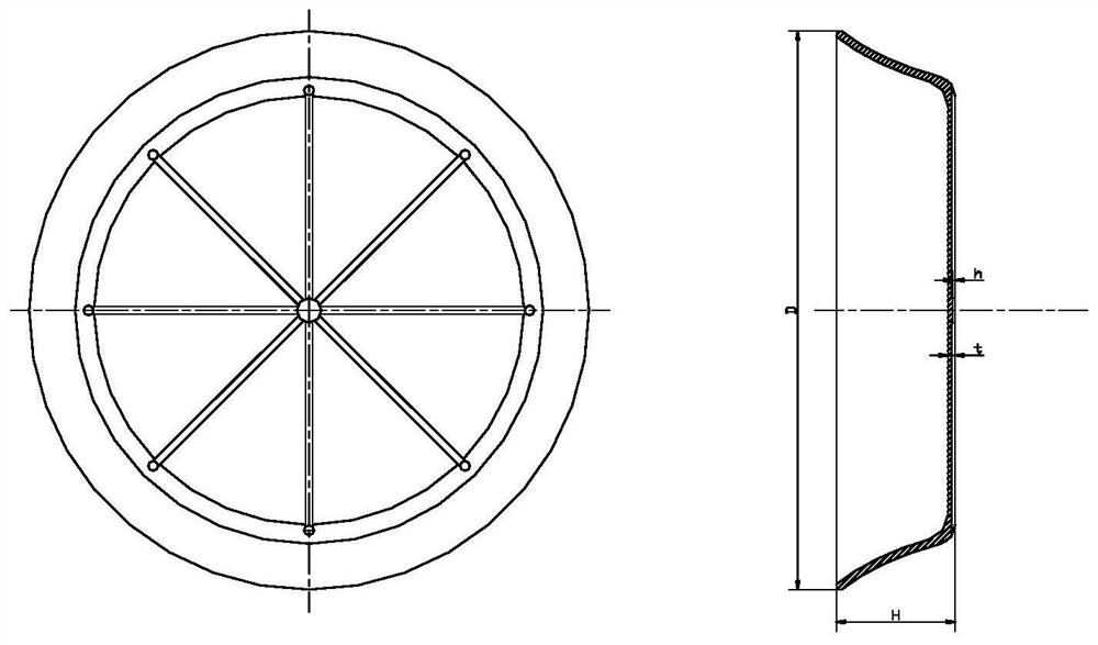
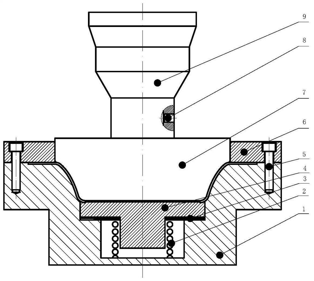
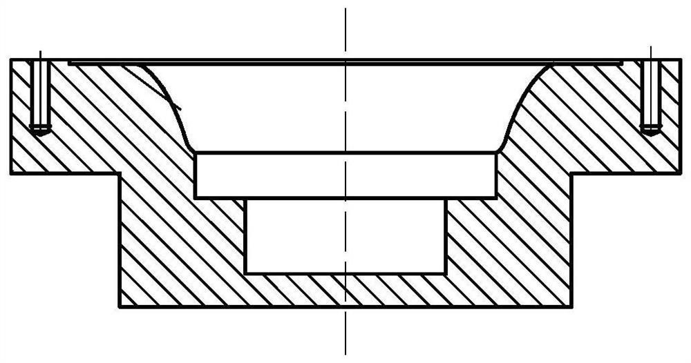
The invention discloses a thin-wall flat-bottom blanking cap with a weakening groove and a forming mold and method thereof. The blanking cap is machined and formed through a special tool mold with anindentation plate, a structure for adjusting the depth of the weakening groove is designed on a tool, the using requirements of blanking cap working conditions with different opening pressures can bemet, the flat-bottom blanking cap and the weakening groove can be machined and formed at a time through stamping equipment, or through blanking cap wall thickness compensation calculation, the spinning thinning amount is taken into consideration in advance during raw material preparation, the blanking cap is manufactured through spinning forming, then petal nicks (namely, the weakening grooves area plurality of radial grooves evenly distributed in the circumferential direction) are formed through the pre-designed indentation plate, the spinning forming of the blanking cap can be achieved, thetwo solutions can be conducted at the same time, and the requirements of different types of production scales can be met. According to the thin-wall flat-bottom blanking cap with the weakening grooveand the forming mold and the method thereof, the machining efficiency is high, and the raw material utilization rate is high.

Description

technical field [0001] The invention belongs to the field of engines, and in particular relates to a thin-walled flat-bottomed plug with weakening grooves, a molding die and a method thereof. Background technique [0002] The thin-walled flat-bottomed cap with weakened grooves is a brand-new structure based on the no-throwing design concept adopted in a new type of engine nozzle. Because the design requires the cap to be thin in the middle and thickened in the bonding section, it is different from the traditional The actual law of spinning forming (due to the large amount of deformation and thinning of the bonding section, the wall thickness is thinner than that of the middle section) is inconsistent, so currently only the mechanical processing and forming scheme can be used for this kind of structural plugging. [0003] Machining with bar material, the main processing process is: raw material procurement, re-inspection → rough machining with large feed rate → stress relief ...

Claims


Application Information

Patent Timeline
Patent Type & Authority Applications(China)
IPC IPC(8): B21D22/02B21D22/16B21D37/10F02K1/78B23P15/00
CPCB21D22/02B21D22/16B21D37/10F02K1/78B23P15/00
Inventor 张英龚军善赵琳瑜尚勇付立新张岩吴军
Owner XIAN AEROSPACEMOTOR MACHINE FACTORY
Learn More