
Parallel spinning device

A technology of parallel connection and pressure plate, which is applied in the field of plastic forming, can solve the problems of low dimensional accuracy and inability to spin small-diameter rotary parts, etc., and achieve the effect of improving the mechanical properties of the surface

Active Publication Date: 2020-03-06
YANSHAN UNIV
View PDF17 Cites 0 Cited by
  • Summary
  • Abstract
  • Description
  • Claims
  • Application Information

AI Technical Summary

Problems solved by technology

The invention patent (notification number CN103128152B) discloses the spinning forming method of the engine shell, which aims to solve the problem that the general three-spinning wheel spinning machine tool cannot spin small-diameter rotary parts, and solve the thin-walled thin-walled high-strength steel material rolled and welded. The problem of low dimensional accuracy of the rotating body part method

Method used


Image

  • Parallel spinning device

Examples


Embodiment Construction

[0015] The technical solutions in the embodiments of the present invention will be clearly and completely described below in conjunction with the accompanying drawings in the embodiments of the present invention. Obviously, the described embodiments are only a part of the embodiments of the present invention, rather than all the embodiments. Based on the embodiments of the present invention, all other embodiments obtained by those of ordinary skill in the art without creative efforts shall fall within the protection scope of the present invention.

[0016] In order to make the above-mentioned objects, features and advantages of the present invention more obvious and understandable, the present invention will be further described in detail below in conjunction with the accompanying drawings and specific embodiments.

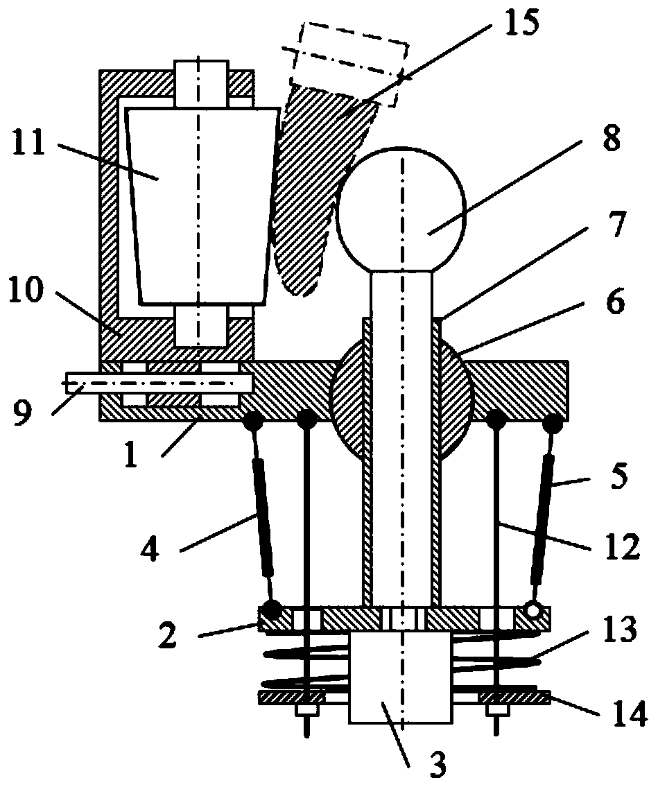
[0017] Such as figure 1 Shown: This embodiment provides a parallel spinning device, including a parallel mechanism and a supporting roller mechanism. The parallel mech...


PUM


Abstract

The invention discloses a parallel spinning device. The parallel spinning device comprises a parallel mechanism and a supporting roller mechanism, the parallel mechanism comprises a machine seat, a moving table, a spinning head, two SPS-type electric cylinders and an SPR-type electric cylinder, the moving table is arranged below the machine seat, one end of each SPS-type electric cylinder is connected with a machine seat ball pair, the other end of each SPS-type electric cylinder is connected with a moving table ball pair, one end of the SPR-type electric cylinder is connected with the machinebase ball pair, the other end of the SPR-type electric cylinder is connected with a moving table rotation pair, and the spinning head comprises a pressure head and a cylinder; and the pressure head is in contact with the concave curved surface of a workpiece, the supporting roller mechanism is arranged above the machine base, the supporting roller mechanism comprises a bracket, the bracket is slidably connected with the machine seat, an opening cavity is formed in the bracket, through holes are formed in the upper and lower wings of the opening cavity respectively, a press roller is rotatablyconnected between the two through holes, and the press roller is in contact with the convex curved surface of the workpiece. The parallel spinning device enables the supporting roller mechanism and the parallel mechanism to be spun and squeezed mutually so as to achieve the machining and manufacture of asymmetric parts and three-dimensional curved-surface workpieces, and the surface mechanical properties of the workpiece are significantly improved.

Description

Technical field [0001] The invention relates to the technical field of plastic forming, in particular to a parallel spinning device. Background technique [0002] Spinning, as a typical continuous partial plastic forming technology, has become a precision technology due to its hydrostatic forming (no impact, vibration and environmental hazards), high product accuracy, good process flexibility, easy realization of mechanization and automation, and material saving. The important development direction of plastic forming technology is to realize the advanced manufacturing technology of thin-walled rotating parts with little and no cutting, which is widely used in the defense industry such as machinery, electronics, chemical industry, automobile and aerospace. The development of spinning technology has also promoted the development of domestic spinning equipment and related technologies. Especially in recent years, the strong demand in the field of defense such as aerospace and aviati...

Claims


Application Information

Patent Timeline
Patent Type & Authority Patents(China)
IPC IPC(8): B21D22/16
Inventor 路懿路扬常泽锋惠立新
Owner YANSHAN UNIV
Learn More