

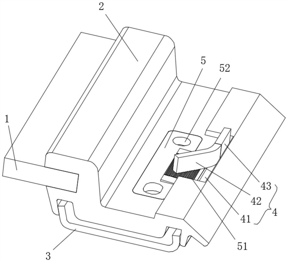
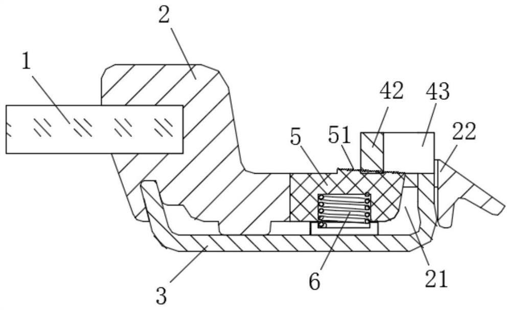
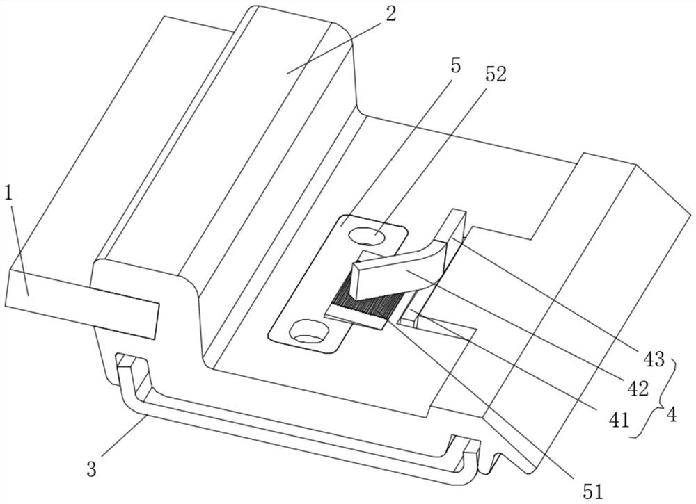
Edge-covered glass assembly with decorative strip
A technology of edging glass and assembly, applied in windshield, transportation and packaging, engine sealing, etc., can solve the problems of difficult to bend assembly, difficult to bend jaws, and high assembly space requirements, and to reduce the size Accuracy requirements, ensuring assembly accuracy requirements, and reducing production costs
- Summary
- Abstract
- Description
- Claims
- Application Information
AI Technical Summary
Problems solved by technology
Method used
Image

Examples
Embodiment Construction
[0024] In the description of the present invention, it should be understood that the orientation or positional relationship indicated by the terms "upper", "lower", "transverse", etc. is based on the orientation or positional relationship shown in the drawings, and is only for the convenience of describing the present invention and simplified descriptions, rather than indicating or implying that the device or element referred to must have a specific orientation, be constructed and operate in a specific orientation, and thus should not be construed as limiting the invention. In the description of the present invention, it should be noted that unless otherwise specified and limited, the terms "connected" and "connected" should be understood in a broad sense, for example, it can be a fixed connection, a detachable connection, or an integral ground connection; it can be directly connected or indirectly connected through an intermediary. In the description of the present invention,...
PUM
 Abstract
Description
Claims
Application Information