Anti-damage uniform storage device for auxiliary cables of coal mining machine and using method
A technology for auxiliary cables and storage devices, which is applied in the directions of transportation and packaging, delivery of filamentous materials, thin material processing, etc., which can solve problems such as inconvenient use, uneven cable storage, and short service life, so as to reduce the cost of use and facilitate The effect of classification storage
- Summary
- Abstract
- Description
- Claims
- Application Information
AI Technical Summary
Problems solved by technology
Method used
Image
Examples
Embodiment 1
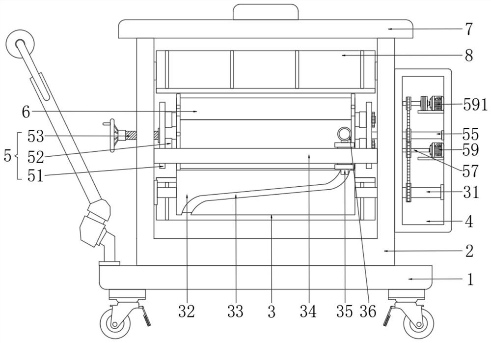
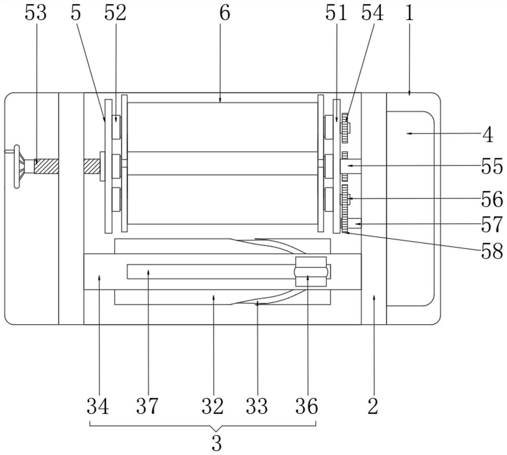
[0029] Embodiment 1: A damage-proof uniform storage device for auxiliary cables of a coal mining machine, please refer to 1 and figure 2 , including the base 1, casters are also provided around the bottom of the base 1, and a push handle is also provided on the left side of the top, which is convenient for the user to push the device to move. It is widely used in this field and will not be described in detail here. The components are all connected to the external power supply through wires. The top of the base 1 is fixed with a support frame 2 with a U-shaped vertical section. The support frame 2 is on the right side of the push handle. A reciprocating guide mechanism 3 is arranged on the front side of the inner cavity, and the reciprocating guide mechanism 3 makes the cables to be stored reciprocate left and right to realize uniform storage. The right side of the support frame 2 is fixedly provided with a housing 4, and one side of the housing 4 is provided with a cover (not...
Embodiment 2
[0030] Embodiment 2: This embodiment is different from the above embodiment, please refer to figure 1 and figure 2 , the reciprocating guide mechanism 3 includes a receiving rotating rod 31, which plays the role of supporting and installing structure, the left end of the receiving rotating rod 31 is movably connected with the front end of the bottom of the inner wall on the left side of the support frame 2 through a bearing, and the right end of the receiving rotating rod 31 It runs through the right side of the support frame 2 and the left side of the casing 4 and is movably connected with the inner wall of the right side of the casing 4 through bearings. The connection between the receiving rotating rod 31 and the supporting frame 2 and the casing 4 is provided with a bearing, and the receiving rotating rod 31 is located in the supporting frame 2 The outer wall of the fixed sleeve is provided with a rotating roller 32, and the outer wall of the rotating roller 32 is provid...
Embodiment 3
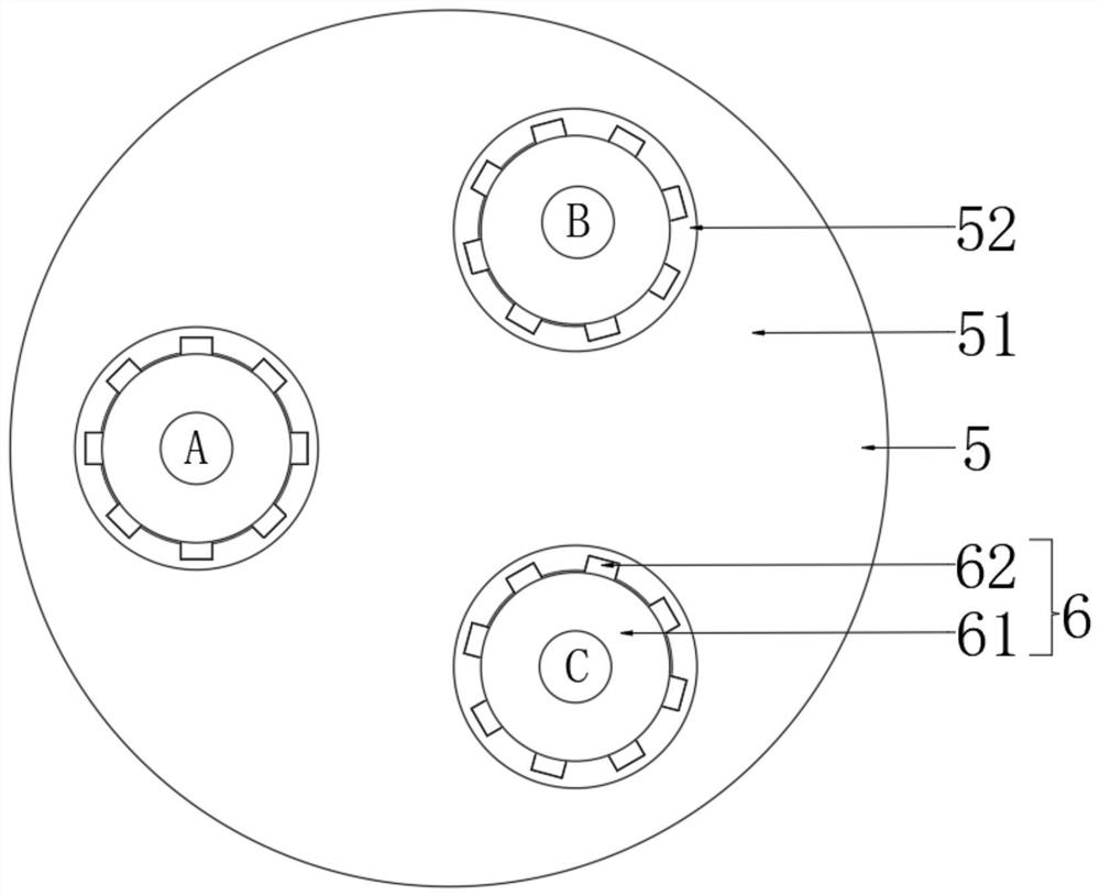
[0031] Embodiment 3: The difference between this embodiment and the above-mentioned embodiment is that please refer to figure 1 and figure 2 , the conversion storage adjustment mechanism 5 includes a receiving plate 51, the receiving plate 51 plays the role of support and installation structure, the number of the receiving plate 51 is two groups, and the two groups of receiving plates 51 are located behind the guide block 34, the left receiving plate 51 The center of the circle on the left side is movably connected with the right end of the screw rod 53 through the bearing, so that the left receiving plate 51 will not be driven to rotate when the screw rod 53 is rotated, and the right receiving plate 51 will be rotated to drive the three groups of storage mechanisms 6 to rotate, and the three groups of storage mechanisms 6 to rotate The screw rod 53 will not be interfered when the left side receiving plate 51 is driven to rotate. The left end thread of the screw rod 53 runs ...
PUM
 Abstract
Description
Claims
Application Information
 - R&D
- Intellectual Property
- Life Sciences
- Materials
- Tech Scout
- Unparalleled Data Quality
- Higher Quality Content
- 60% Fewer Hallucinations
Browse by: Latest US Patents, China's latest patents, Technical Efficacy Thesaurus, Application Domain, Technology Topic, Popular Technical Reports.
© 2025 PatSnap. All rights reserved.Legal|Privacy policy|Modern Slavery Act Transparency Statement|Sitemap|About US| Contact US: help@patsnap.com


