Iron core plate annealing clamp

An iron core sheet and annealing technology, which is applied in the field of transformer production, can solve the problems of annealing, difficulty in annealing operation, and inability to stack iron core sheets into piles, etc., and achieve the effect of guaranteeing the technical effect

Active Publication Date: 2020-12-04
JIANGXI GANDIAN ELECTRIC
View PDF9 Cites 2 Cited by
  • Summary
  • Abstract
  • Description
  • Claims
  • Application Information

AI Technical Summary

Problems solved by technology

Since the thickness of the core pieces is very thin, the annealing operation cannot stack the core pieces into a pile for annealing, and it is difficult to place the core pieces at intervals, which brings certain difficulties to the on-site annealing operation

Method used


Image

  • Iron core plate annealing clamp
  • Iron core plate annealing clamp
  • Iron core plate annealing clamp

Examples


Embodiment Construction

[0017] In order to facilitate the understanding of the present invention, the present invention will be described more fully below with reference to the associated drawings. A preferred embodiment of the invention is shown in the drawings. However, the present invention can be embodied in many different forms and is not limited to the embodiments described herein. Rather, these embodiments are provided so that the disclosure of the present invention will be thorough and complete.

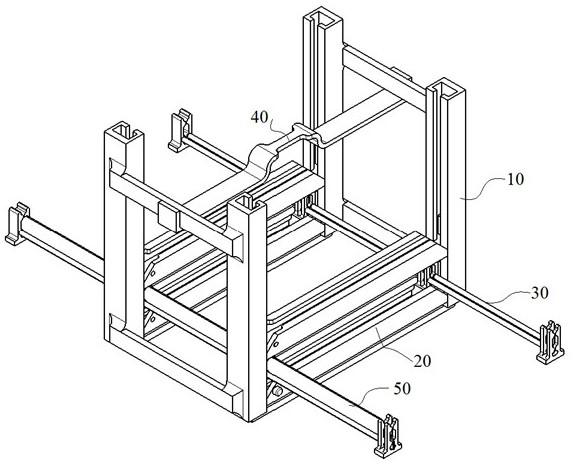
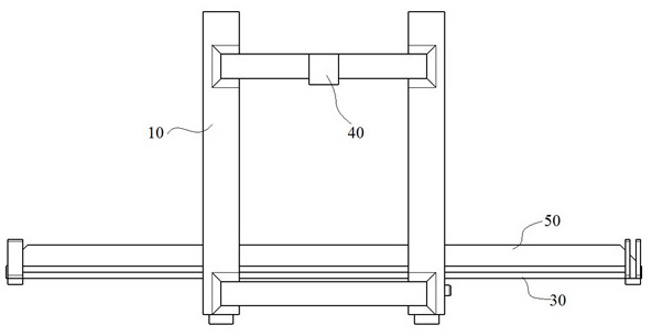
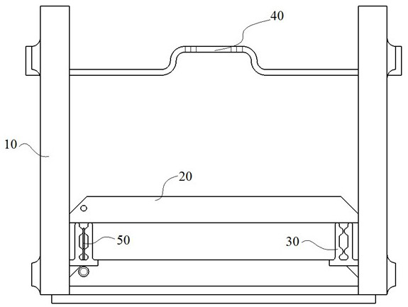
[0018] see Figure 1-Figure 4 The iron core piece annealing jig shown includes frame 10 , beam 20 , bracket 30 and handle 40 , beam 20 is installed on frame 10 , bracket 30 is installed on beam 20 , and handle 40 is installed on top of frame 10 .

[0019] Frame 10 comprises column 11, vertical T groove 12, bottom beam 13 and side beam 14, and column 11 has four, and column 11 center has vertical T groove 12, and a pair of bottom beam 13 and four side beams 14 combine four Uprights 11 are connecte...


PUM


Abstract

The invention discloses an iron core plate annealing clamp and belongs to the field of transformer production. The iron core plate annealing clamp comprises a frame, cross beams, supports and a handle, the cross beams are mounted on the frame, the supports are mounted on the cross beams, and the handle is mounted at the top of the frame. The frame comprises stand columns, vertical T-shaped grooves, bottom beams and side beams, the number of the stand columns is four, the vertical T-shaped grooves are formed in the centers of the stand columns, and the four stand columns are connected to form the whole frame through the pair of bottom beams and the four side beams. The cross beams comprise beam bodies, horizontal T-shaped grooves, gaps, sliding grooves and side tables, the horizontal T-shaped grooves are formed in the middles of the beam bodies, the supports are installed in the horizontal T-shaped grooves, the gaps are formed in one ends of the beam bodies and used for being embedded into the supports, the sliding grooves are formed in the two ends of the beam bodies, and the side tables are arranged at the outer ends of the sliding grooves. Each support comprises a connecting rod,vertical grooves, round heads and sliding blocks, the connecting rod of each support is connected with the multiple vertical grooves, and the corresponding sliding blocks are arranged at the bottomsof the two vertical grooves in the middle of each support and installed in the corresponding horizontal T-shaped grooves. The handle comprises a transverse rod, side hooks and a hand shank, the handleis installed on the side beams at the top of the frame, the side hooks are arranged at the two ends of the transverse rod and hook the side beams, and the hand shank is arranged in the middle of thetransverse rod.

Description

technical field [0001] The invention belongs to the technical field of transformer production, and in particular relates to an annealing jig for an iron core sheet. Background technique [0002] Transformer cores are usually made of stacked core sheets, which are usually cut from steel coils. The cut core sheets usually need to be annealed to eliminate the stress brought by the cutting operation to the core sheets. Since the thickness of the core sheets is very thin, the annealing operation cannot stack the core sheets into a pile for annealing, and it is difficult to place the core sheets at intervals, which brings certain difficulties to the on-site annealing operation. Contents of the invention [0003] The present invention provides an annealing jig for iron core sheets to solve the above-mentioned problems in the background technology. [0004] The technical problem solved by the present invention adopts following technical scheme to realize: [0005] An annealing f...

Claims


Application Information

Patent Timeline
Patent Type & Authority Applications(China)
IPC IPC(8): C21D9/46C21D1/26
CPCC21D9/46C21D1/26
Inventor 张爱民杨强
Owner JIANGXI GANDIAN ELECTRIC
Why Eureka
Try Eureka