
Laying device capable of reducing labor force and applied to building construction

A technology for building construction and laying devices, which is applied to buildings, roads, road repair and other directions, can solve the problems of reducing the laying efficiency of laying work, the laying effect, the low laying efficiency, and the practicability of laying devices, etc. Dust removal effect, the effect of improving laying efficiency

Inactive Publication Date: 2020-12-04
安徽翔誉千秋建设集团有限公司
View PDF6 Cites 9 Cited by
  • Summary
  • Abstract
  • Description
  • Claims
  • Application Information

AI Technical Summary

Problems solved by technology

[0007] The purpose of the present invention is to provide a kind of laying device that can reduce labor force that is applied to building construction, to solve the above-mentioned background technology, the overall laying efficiency of the existing laying device is low, and it is inconvenient to carry out continuous automatic laying of floor tiles. When laying floor tiles, it is not convenient to apply concrete mortar evenly on the area to be laid, thereby reducing the laying efficiency of the laying work and the overall laying effect. As a result, a large amount of dust generated during the laying process floods the working area, which brings unnecessary impact to the surrounding staff, thereby reducing the practicality of the laying device itself

Method used


Image

  • Laying device capable of reducing labor force and applied to building construction
  • Laying device capable of reducing labor force and applied to building construction
  • Laying device capable of reducing labor force and applied to building construction

Examples


Embodiment Construction

[0029] The following will clearly and completely describe the technical solutions in the embodiments of the present invention with reference to the accompanying drawings in the embodiments of the present invention. Obviously, the described embodiments are only some, not all, embodiments of the present invention. Based on the embodiments of the present invention, all other embodiments obtained by persons of ordinary skill in the art without making creative efforts belong to the protection scope of the present invention.

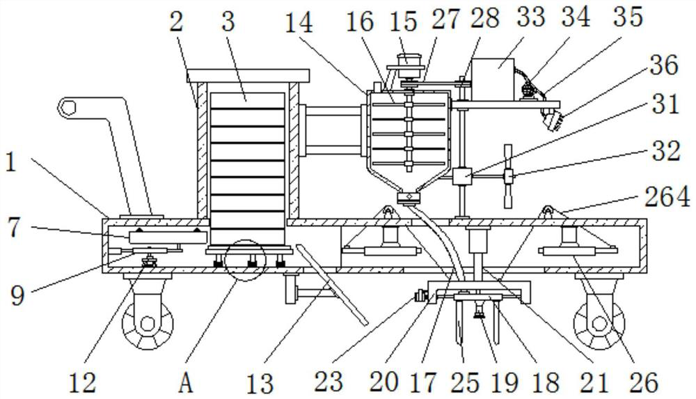
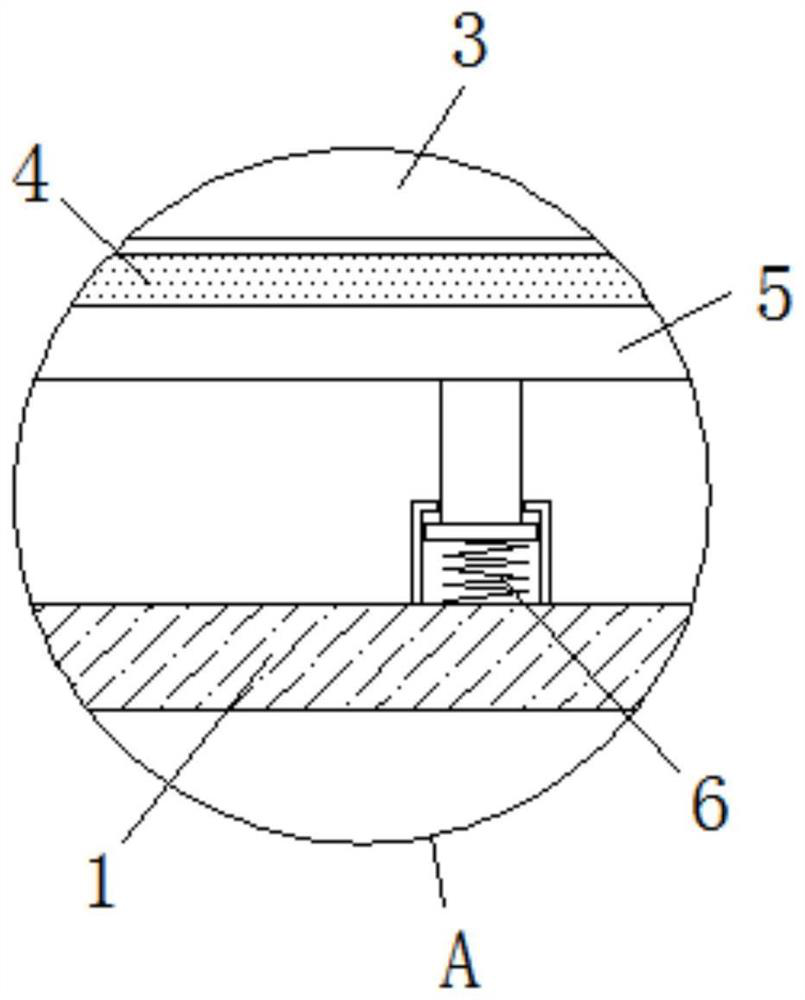
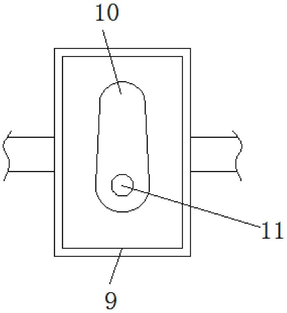
[0030] see Figure 1-7, the present invention provides a technical solution: a laying device that can reduce labor force and is applied to building construction, including a mobile base 1, a placing frame 2, a floor tile body 3, a sponge pad 4, a moving plate 5, an adjusting spring 6, and a pushing plate 7. Roller 8, movable frame 9, cam 10, transmission rod 11, first servo motor 12, guide inclined plate 13, raw material box 14, drive motor 15, stirring rod 16...


PUM


Abstract

The invention discloses a laying device capable of reducing a labor force and applied to building construction. The device comprises a movable base, a placement frame, a floor tile body and a water pump. The placement frame is fixedly installed at the upper end of the movable base, the floor tile body is installed in the placement frame, and a pushing plate is installed on the left side of the floor tile body; rollers are mounted at upper end of the pushing plate, an adjusting rod is installed on the rear side of the transverse plate, a scraping plate is fixedly installed on the side of the lower end of the transverse plate, a water tank is fixedly installed on the right side of the upper end of the raw material box, a water pump is installed on the right side of the water tank, and a connecting pipe is fixedly connected to the right side of the water pump; and the lower end of the connecting pipe is fixedly mounted at the left end of a sprinkler head. According to the laying device capable of reducing the labor force and applied to building construction, laying efficiency of floor tiles can be improved, meanwhile, concrete mortar can be evenly smeared to a to-be-laid area, and a good dust falling protection effect can be achieved when the floor tiles are laid.

Description

technical field [0001] The invention relates to the technical field related to building construction, in particular to a laying device that can reduce labor force and is applied in building construction. Background technique [0002] Building construction refers to the production activities in the implementation stage of engineering construction. It is the construction process of various buildings. With the development of society, various buildings are widely constructed. Laying floor tiles can effectively ensure the flatness of the road surface and improve the overall aesthetics of the building. In the past when laying floor tiles, most of the floor tiles were manually pulled to the corresponding laying position, and then manually pulled Floor tiles are laid on the ground, which greatly increases the labor force. Therefore, automatic laying devices are usually used to assist in the installation of floor tiles. [0003] Yet existing laying device has the following problems:...

Claims


Application Information

Patent Timeline
IPC IPC(8): E01C19/52E01C19/48
CPCE01C19/48E01C19/4866E01C19/52E01C2301/50
Inventor 寿仟慧
Owner 安徽翔誉千秋建设集团有限公司
Learn More