Ground drilling sectional type grouting device

A segmented grouting technology, which is applied to drilling equipment and methods, drilling equipment, drilling pipes, etc., can solve problems such as insufficient grouting pressure, endangering the life safety of staff, and rising of grout, so as to improve the sealing performance and firmness, improve the plugging effect, and improve the stability

Active Publication Date: 2020-12-04
北京大地高科地质勘查有限公司
View PDF9 Cites 7 Cited by
  • Summary
  • Abstract
  • Description
  • Claims
  • Application Information

AI Technical Summary

Problems solved by technology

[0002] At present, in the process of mining coal mines, it is often necessary to drill holes. The formation of holes can be used in many aspects, such as using drill holes for anchoring when performing support, or using drill holes for gas drainage. However, at present, due to the loose and broken coal body or the dynamic change of the crack structure around the borehole, it is easy to collapse the hole when the hole is formed, which endangers the life safety of the staff.
[0003] In order to reduce the occurrence of this kind of situation, the coal body can be reinforced first. Generally speaking, drilling and grouting is the best way of reinforcement. However, direct grouting will cause the grout to rise up, and the grouting pressure is not enough to form Effective grout layer, if the existing bladder is used to seal the hole and then grouted, because the bladder cannot be in close contact with the hole wall, the high-pressure slurry will flow out from the gap between the bladder and the hole wall, thereby Does not form a good seal

Method used


Image

  • Ground drilling sectional type grouting device
  • Ground drilling sectional type grouting device
  • Ground drilling sectional type grouting device

Examples


Embodiment Construction

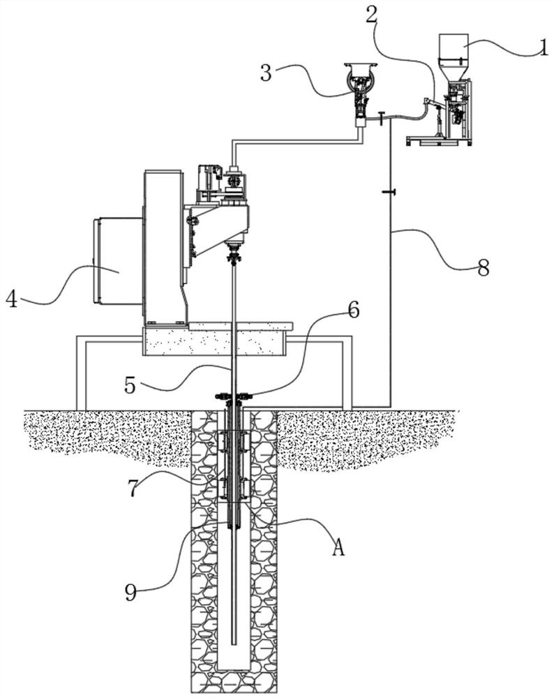
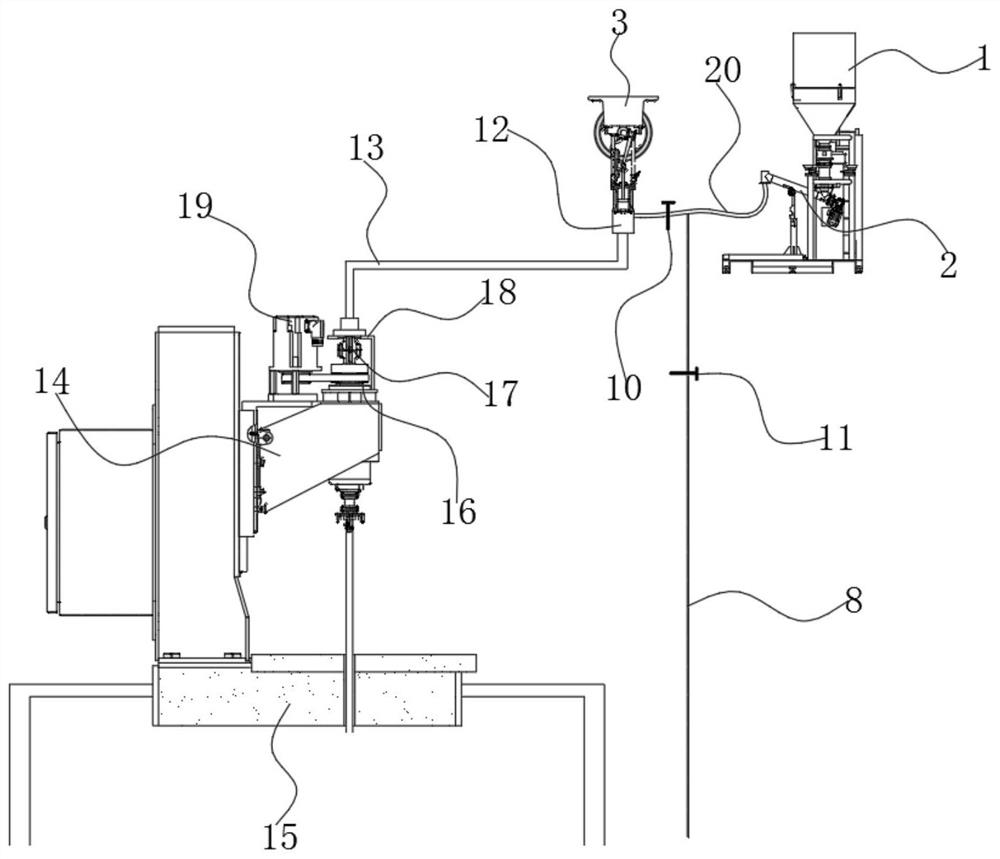
[0033] see Figure 1~5 , in an embodiment of the present invention, a ground drilling segmented grouting equipment, which includes a grout tank 1, a grouting main pipe 5, a reaming assembly 6, a liquid injection pipe 7, a low-pressure grouting pipe 8, an upper support plug component 32 and the lower support plugging component 33, wherein, the grouting main pipe 5 and the low-pressure grouting pipe 8 are both supplied with grout by the grout tank 1;

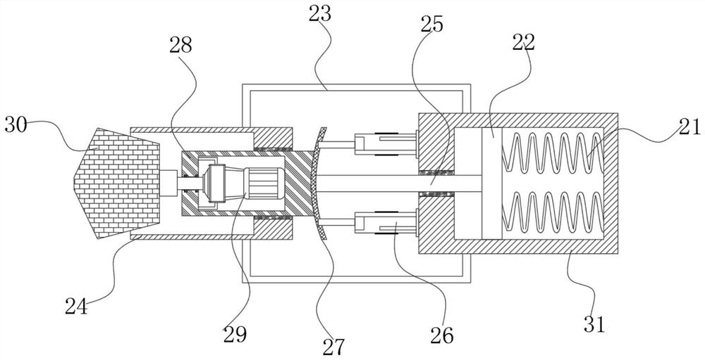
[0034] The grouting main pipe 5 is rotatably arranged in the centering sleeve 9, and the upper support block assembly 32 and the lower support block assembly 33 are arranged on the outer circumference of the centering sleeve 9, which are used to set the centering sleeve The cylinder 9 is supported in the inner wall of the borehole, that is to say, the upper support plugging assembly 32 and the lower support plugging assembly 33 are supported and attached to the inner wall of the borehole at the initial stage. After the hole is rea...


PUM


Abstract

The invention discloses a ground drilling sectional type grouting device. The ground drilling sectional type grouting device comprises a slurry tank, a grouting main pipe, a reaming assembly, a liquidinjection pipe, a low-pressure grouting pipe, an upper supporting and blocking assembly and a lower supporting and blocking assembly, wherein the slurry tank supplies slurry to the grouting main pipeand the low-pressure grouting pipe, the grouting main pipe is rotationally arranged in a centralizing sleeve, and the upper supporting and blocking assembly and the lower supporting and blocking assembly are arranged on the outer circumference of the centralizing sleeve; the reaming assembly is further arranged on the grouting main pipe, and the reaming assembly can be driven to rotate for reaming by driving the grouting main pipe to rotate; after reaming, liquid is injected into the upper supporting and blocking assembly and the lower supporting and blocking assembly through the liquid injection pipe so that the upper supporting and blocking assembly and the lower supporting and blocking assembly can expand and be correspondingly embedded into reamed holes, and the low-pressure groutingpipe can inject slurry into the space between the upper supporting and blocking assembly and the lower supporting and blocking assembly so as to form a sealed hole; and then the grouting main pipe injects slurry into the bottom of the sealed hole, and sectional type grouting is achieved.

Description

technical field [0001] The invention belongs to the technical field of segmental grouting, and in particular relates to segmental grouting equipment for ground drilling. Background technique [0002] At present, in the process of mining coal mines, it is often necessary to drill holes. The formation of holes can be used in many aspects, such as using drill holes for anchoring when performing support, or using drill holes for gas drainage. However, at present, due to the loose and broken coal body or the dynamic change of the crack structure around the borehole, the hole collapse is easy to occur when the hole is formed, which endangers the life safety of the staff. [0003] In order to reduce the occurrence of this kind of situation, the coal body can be reinforced first. Generally speaking, drilling and grouting is the best way of reinforcement. However, direct grouting will cause the grout to rise up, and the grouting pressure is not enough to form Effective grout layer, ...

Claims


Application Information

Patent Timeline
Patent Type & Authority Applications(China)
IPC IPC(8): E21B17/10E21B7/28E21B33/138
CPCE21B17/1078E21B7/28E21B33/138
Inventor 肖明国张彪黄辅强孙红波王越阴慧胜历彦福
Owner 北京大地高科地质勘查有限公司
Why Eureka
Try Eureka