
Combustion control system, ignition method, and heat treatment equipment

A control system and controller technology, which is applied in the combustion method, combustion ignition, lighting and heating equipment, etc., can solve the problems of low power point not igniting, product quality problems, and high furnace temperature, so as to achieve stable gas output and avoid Effects of accumulation or excessive temperature

Active Publication Date: 2020-12-04
江苏丰东热技术有限公司
View PDF9 Cites 0 Cited by
  • Summary
  • Abstract
  • Description
  • Claims
  • Application Information

AI Technical Summary

Problems solved by technology

[0003] The existing combustion system scheme is designed to have a large production capacity, but when actually processing products with a small production capacity, due to the particularity of the ignition of the burner, it is easy to cause the temperature in the furnace body to be too high when the ignition is performed with a low power, resulting in quality problems of the product
If a lower power is used to ignite to ensure that the temperature does not exceed the temperature, there will be a situation where the low power point does not ignite. Repeated igniting will lead to an increase in combustible gas in the furnace. When the combustible gas accumulates to a certain amount, an explosion will occur. danger

Method used


Image

  • Combustion control system, ignition method, and heat treatment equipment
  • Combustion control system, ignition method, and heat treatment equipment
  • Combustion control system, ignition method, and heat treatment equipment

Examples


no. 1 example

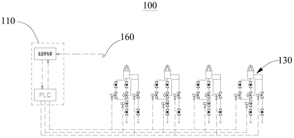
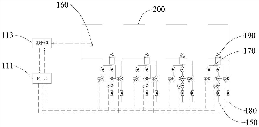
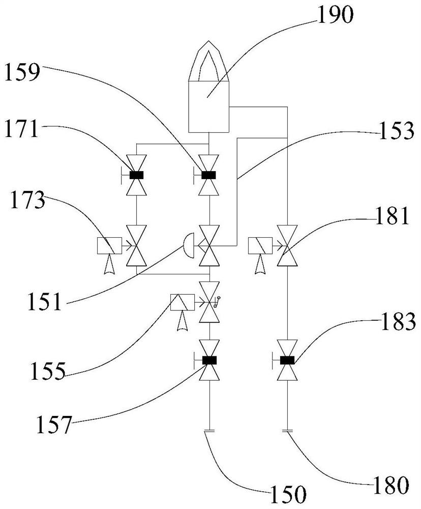
[0035] Please refer to Figure 1 to Figure 3 , this embodiment provides a combustion control system 100, which can ensure successful ignition and is more stable and reliable.

[0036] The combustion control system 100 provided in this embodiment includes a controller 110 and at least one gas control assembly 130. The gas control assembly 130 includes a gas pipeline 150, an ignition pipeline 170, an air pipeline 180 and a burner 190. The burner 190 uses Installed in the furnace body 200, the gas pipeline 150 and the air pipeline 180 are both connected to the burner 190, the gas pipeline 150 is provided with a gas proportional valve 151, and the gas proportional valve 151 is provided with a valve connected to the air pipeline 180 Regulating pipeline 153; two ends of ignition pipeline 170 are respectively connected with gas pipeline 150 on both sides of gas proportional valve 151 to form a branch of gas pipeline 150, and ignition pipeline 170 is provided with ignition solenoid va...

no. 2 example

[0066] This embodiment provides a heat treatment device, including a furnace body 200 and a combustion control system 100, wherein the basic structure and implementation principle of the combustion control system 100 are the same as those of the combustion control system 100 provided in the first embodiment, and this embodiment does not mention Reference can be made to the first embodiment here.

[0067] The combustion control system 100 includes a controller 110 and at least one gas control assembly 130. The gas control assembly 130 includes a gas pipeline 150, an ignition pipeline 170, an air pipeline 180 and a burner 190. The burner 190 is used to be arranged on the furnace body 200 Inside, the gas pipeline 150 and the air pipeline 180 are both connected to the burner 190, the gas pipeline 150 is provided with a gas proportional valve 151, and the gas proportional valve 151 is provided with an adjustment pipeline 153 connected with the air pipeline 180; The two ends of the ...


PUM


Abstract

The embodiment of the invention provides a combustion control system, an ignition method and heat treatment equipment, and relates to the field of heat treatment equipment. The combustion control system comprises a controller and at least one gas control assembly, the gas control assembly comprises a gas pipeline, an ignition pipeline, an air pipeline and a combustor, and the gas pipeline and theair pipeline are both connected with the combustor; a gas proportional valve is arranged on the gas pipeline, and an adjusting pipeline connected with the air pipeline is arranged on the gas proportional valve; and the two ends of the ignition pipeline are connected with the parts, on the two sides of the gas proportional valve, of the gas pipeline respectively to form branches of the gas pipeline, an ignition electromagnetic valve and an ignition adjusting valve are arranged on the ignition pipeline, and the ignition electromagnetic valve is electrically connected with the controller. Due tothe fact that the independent ignition pipeline is adopted and the ignition adjusting valve is arranged for adjustment, gas output is more stable, it is guaranteed that ignition of the combustor can be successful each time, ignition can be conducted in time during ignition, and accumulation of combustible gas or temperature exceeding is avoided.

Description

technical field [0001] The invention relates to the field of heat treatment equipment, in particular to a combustion control system, an ignition method and heat treatment equipment. Background technique [0002] In the heat treatment equipment industry, the stability of the combustion system directly affects the quality of the product; since the burner needs to be ignited with low power when it is in the ignition state, it will switch to the high power state after the burner is successfully ignited for heat treatment. [0003] The existing combustion system scheme is designed to have a large production capacity, but when actually processing products with a small production capacity, due to the particularity of the ignition of the burner, it is easy to cause the temperature in the furnace body to be too high when the ignition is performed with a low power, resulting in quality problems of the product. If a lower power is used to ignite to ensure that the temperature does not ...

Claims


Application Information

Patent Timeline
Patent Type & Authority Applications(China)
IPC IPC(8): F23N5/00F23Q9/00
CPCF23N5/00F23Q9/00
Inventor 盛克拉朱海林陈云飞
Owner 江苏丰东热技术有限公司
Learn More