
Low-temperature dry distillation process for granulated oil shale based on walking beam furnace

A walking furnace and oil shale technology, which is applied in the field of oil shale dry distillation, can solve the problems of unutilized latent heat, low operation rate, and large proportion of heavy oil, so as to reduce purification and storage and transportation links, and facilitate large-scale production. The effect of area extension and effective oxygen content

Inactive Publication Date: 2013-05-08
CHINA NAT HEAVY MACHINERY RES INSTCO
View PDF1 Cites 5 Cited by
  • Summary
  • Abstract
  • Description
  • Claims
  • Application Information

AI Technical Summary

Problems solved by technology

[0004] There are three typical techniques for carbonization of small particle oil shale in foreign countries. One is the ATP furnace (Alberea-Taciuk Processor) in Australia. This device is a solid heat carrier rotary carbonization furnace with huge equipment, complex structure and power consumption Large, unstable operation, often shut down for maintenance, the operating rate is only about 50%, and the longest continuous operation was only 96 days
One is the Galoter furnace in Estonia, which can process 0-25mm oil shale, with a processing capacity of 3000t / d. The problem with the equipment is that the operation rate is not high, the proportion of heavy oil is large, there are mechanical operations, oil and gas Dust removal and flue gas dust removal and other issues
The third is the Tosco-II oil shale dry distillation technology developed by Tosco Corporation of the United States, which is used to process small particle oil shale. This system uses ceramic balls as the heat carrier, and the oil recovery rate reaches 90%. The problems with this equipment are: : High investment in equipment, large amount of maintenance, low thermal efficiency, and the latent heat (fixed carbon) in oil shale semi-coke is not utilized
The device uses thermal cycle gas to exchange heat with oil shale, part of the heat is lost in the external pipeline circulation, the heat utilization rate is low, and the equipment structure is complex

Method used


Image

  • Low-temperature dry distillation process for granulated oil shale based on walking beam furnace

Examples


Embodiment Construction

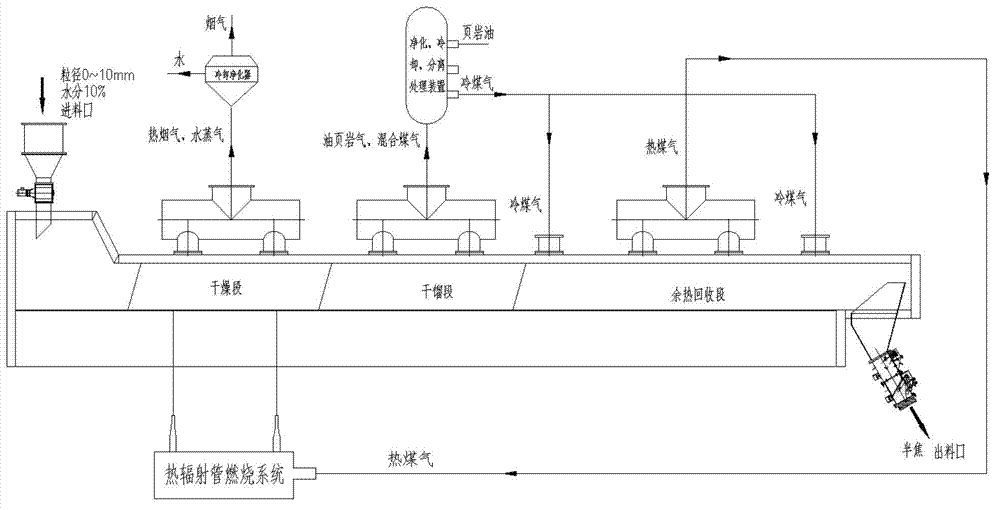
[0021] The present invention will be further described below in conjunction with the accompanying drawings.

[0022] With reference to accompanying drawing, a kind of small particle oil shale low-temperature dry distillation process based on walking furnace comprises the following steps:

[0023] In the first step, the 0-10mm oil shale material enters the walking furnace through the feeding device;

[0024] In the second step, the oil shale material is sent to the drying section for drying with the advancement of the stepping material bed. The radiant heat from the radiant tube combustion system heats the material to 180-200 degrees to complete the oil shale material. Drying and dehydration, the removed water vapor and hot flue gas are discharged after cooling the purifier;

[0025] In the third step, the dried oil shale material enters the dry distillation pyrolysis section, and is heated to 480-500 °C by the radiant heat from the radiant tube combustion system to pyrolyze t...


PUM


Abstract

The invention discloses a low-temperature dry distillation process for granulated oil shale based on a walking beam furnace. The low-temperature dry distillation process comprises the following steps of: heating up the granulated oil shale to 200 DEG C for drying to remove the moisture in the material under the condition of isolating air by adopting a heat radiant tube combustion technology as a material heating way; continuously heating up the material to 500 DEG C, so that the oil shake material is thermally decomposed to form solid semicoke; and purifying and recycling the separated volatile matters to obtain the products such as shale oil and coal gas, wherein the coal gas is used as the fuel of the heat accumulating type radiant tube after absorbing the waste heat of the semicoke. The low-temperature dry distillation process disclosed by the invention is simple in process, low in energy consumption, free of pollution and high in product quality.

Description

technical field [0001] The invention belongs to the technical field of oil shale dry distillation, and in particular relates to a low-temperature dry distillation process of small particle oil shale based on a walking furnace. Background technique [0002] At present, the techniques used for oil shale dry distillation are divided into solid heat carrier dry distillation method and gas heat carrier dry distillation method. However, most retort processes at home and abroad can only retort particles with a diameter of more than 10mm. Small particles with a diameter of less than 10mm have small particles, small space between materials, and poor air permeability. Furnace blockage and coking make the retort furnace unable to operate normally, so small particles of oil shale are discarded, and the resource waste rate reaches more than 20%. [0003] There are several foreign oil shale retort technologies. The Petrosix retort technology is an oil shale retort method developed by Pet...

Claims


Application Information

Patent Timeline
Patent Type & Authority Applications(China)
IPC IPC(8): C10B53/06C10B57/00C10G1/00
CPCY02P20/129
Inventor 徐鸿钧李国莉姜永涛赵玉良
Owner CHINA NAT HEAVY MACHINERY RES INSTCO
Learn More