Burner and gas stove

A burner and gas stove technology, which is applied in the kitchen field, can solve the problems of gas stove shell bottom pollution, etc., and achieve the effects of reducing exhaust gas emission indicators, sufficient replenishment, and sufficient gas combustion

Pending Publication Date: 2020-12-04
GREE ELECTRIC APPLIANCES INC
View PDF0 Cites 2 Cited by
  • Summary
  • Abstract
  • Description
  • Claims
  • Application Information

AI Technical Summary

Problems solved by technology

[0004] The purpose of the present invention is to provide a burner and a gas cooker to solve the problem of pollution caused by the shell bottom of the gas cooker

Method used


Image

  • Burner and gas stove
  • Burner and gas stove
  • Burner and gas stove

Examples


Embodiment Construction

[0024] In order to better understand the purpose, structure and function of the present invention, a burner and a gas stove of the present invention will be further described in detail below in conjunction with the accompanying drawings.

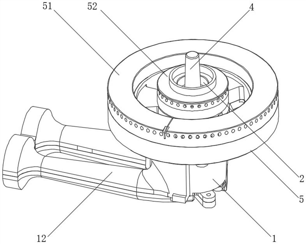
[0025] The gas cooker of the present invention includes a casing. The top surface of the housing is a panel, and is arranged in the stove hole such as figure 1 As shown in the burner, the burner is ignited by the igniter to heat the pan on the support.

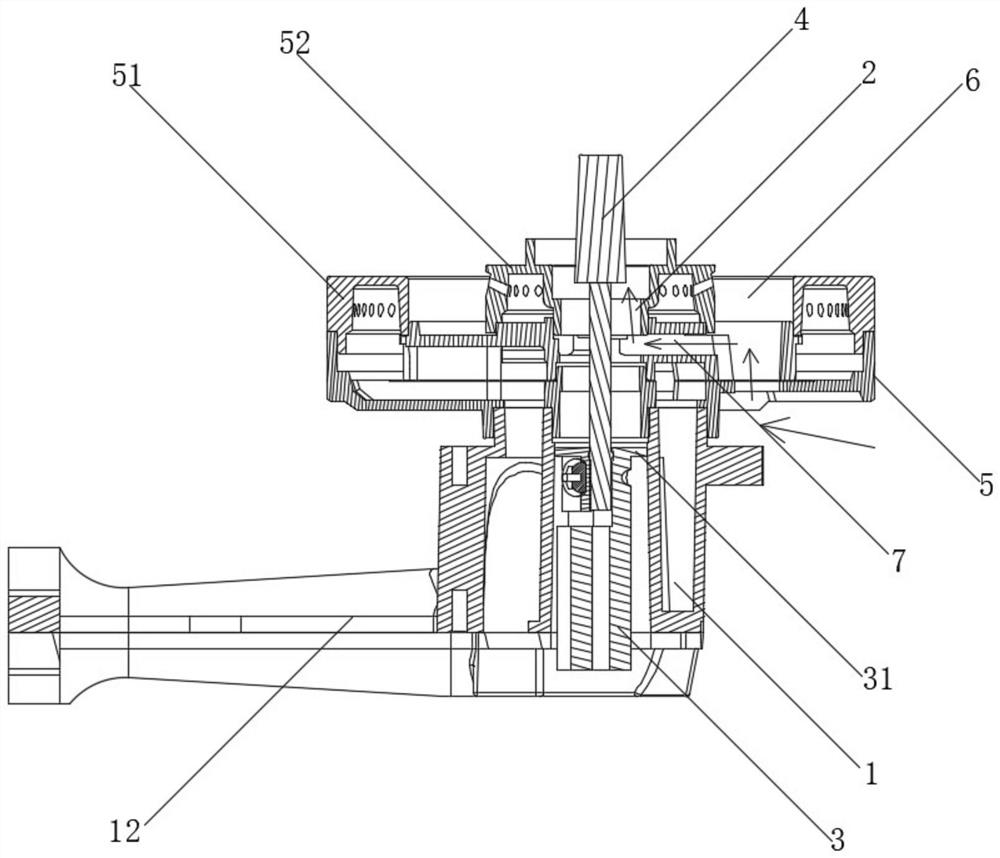
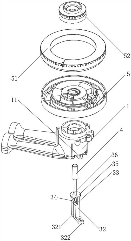
[0026] combine figure 2 and image 3 As shown, the burner includes a burner, and a through hole 2 is formed in the middle of the burner; a baffle 31 is arranged in the through hole 2, and the baffle 31 seals the through hole 2, and the baffle 31 is provided with an anti-drying burn components.

[0027] The baffle plate 31 is fixed on the fixed frame 3 . Fixture 3 comprises main body 32, and main body 32 upper end is formed with splicing portion 33, and splicing portion 33 side is fixed...


PUM


Abstract

The invention discloses a burner and a gas stove. The burner comprises a furnace end; a through hole is formed in the middle of the furnace end; a baffle is arranged in the through hole and blocks thethrough hole; and a dry burning preventing assembly is arranged in the through hole. The central hole of the burner is blocked to prevent soup and dirt from falling into the gas stove shell in the cooking process.

Description

technical field [0001] The invention belongs to the kitchen field, and in particular relates to a burner and a gas stove. Background technique [0002] Gas stoves have become indispensable cooking utensils in modern family kitchens. With the gradual strengthening of people's safety awareness, the safety requirements for cooking utensils are also getting higher and higher. When dry burning occurs in the appliance, the gas stove will automatically cut off the gas and turn off the flame to prevent accidents) has become the best choice for many users. But the design of the burner is particularly important. In order to reduce the temperature of the anti-dry probe itself, the center of the furnace head where the anti-dry probe is installed is generally made with a through hole to facilitate the circulation of air and help reduce the temperature of the anti-dry probe itself. , the disadvantage of this design is that soup and dirt can easily fall into the bottom of the shell from t...

Claims


Application Information

Patent Timeline
Patent Type & Authority Applications(China)
IPC IPC(8): F24C3/08F24C3/12F23D14/46F23D14/58
CPCF23D14/46F23D14/58F24C3/085F24C3/126
Inventor 邓祥王光汉周文通孙帅段聪聪王运发
Owner GREE ELECTRIC APPLIANCES INC
Why Eureka
Try Eureka