Fingerprint identification attendance equipment based on Internet of Things

A technology of fingerprint recognition and attendance equipment, applied in mechanical equipment, character and pattern recognition, registration/instruction and other directions, can solve the problems of wasting employee time, unable to recognize fingers, low recognition rate of dry fingers, etc., to achieve easy entry, saving The effect of the time of attendance punching

Inactive Publication Date: 2020-12-04
刘鹏程
View PDF5 Cites 3 Cited by
  • Summary
  • Abstract
  • Description
  • Claims
  • Application Information

AI Technical Summary

Problems solved by technology

[0003] Due to the limitations of the fingerprint collection principle, it is difficult for optical fingerprint collectors to collect clear fingerprint images for dry fingers, resulting in the low recognition rate of dry fingers and high rejection rate of this product. The drier the fingers, the more prominent this problem , especially in the cold climate in northern winter, many people’s fingers cannot be recognized due to dry fingers. Secondly, when registering fingerprints, the strength and range of fingers pressing on the recording board may be uneven. Interlacing forces will be generated, which will cause fingerprints to be difficult to identify on the surface of the recording board, and need to be entered again, which reduces the efficiency of punching cards and wastes employee time. Therefore, those skilled in the art provide a fingerprint recognition attendance device based on the Internet of Things to solve Problems raised in the background art above

Method used


Image

  • Fingerprint identification attendance equipment based on Internet of Things
  • Fingerprint identification attendance equipment based on Internet of Things
  • Fingerprint identification attendance equipment based on Internet of Things

Examples


Embodiment Construction

[0020] The following will clearly and completely describe the technical solutions in the embodiments of the present invention with reference to the accompanying drawings in the embodiments of the present invention. Obviously, the described embodiments are only some, not all, embodiments of the present invention. Based on the embodiments of the present invention, all other embodiments obtained by persons of ordinary skill in the art without making creative efforts belong to the protection scope of the present invention.

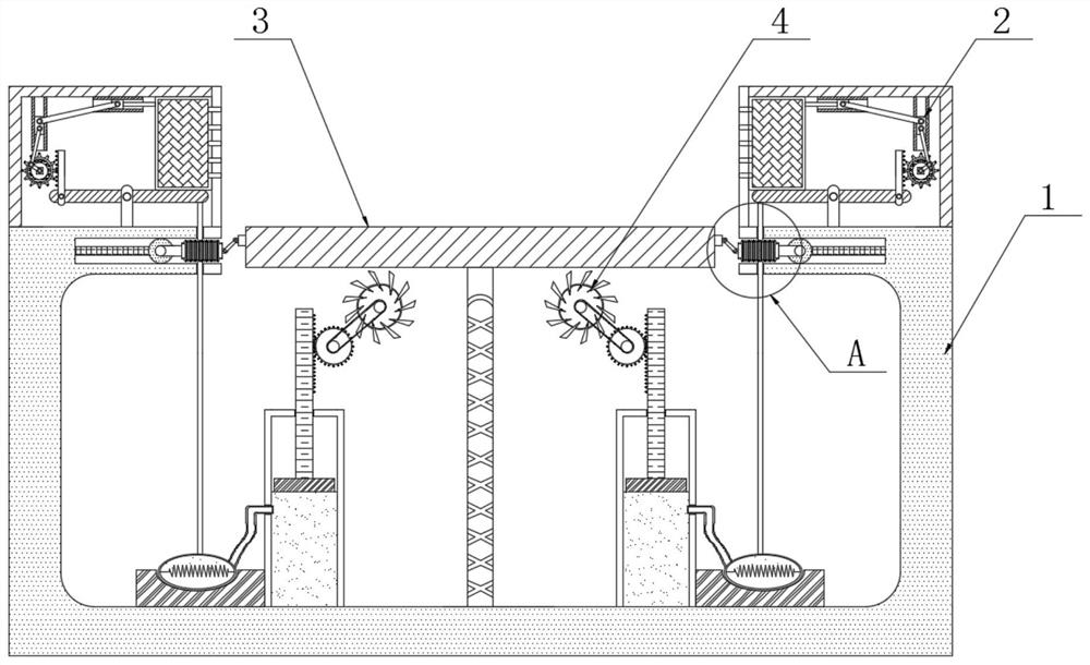
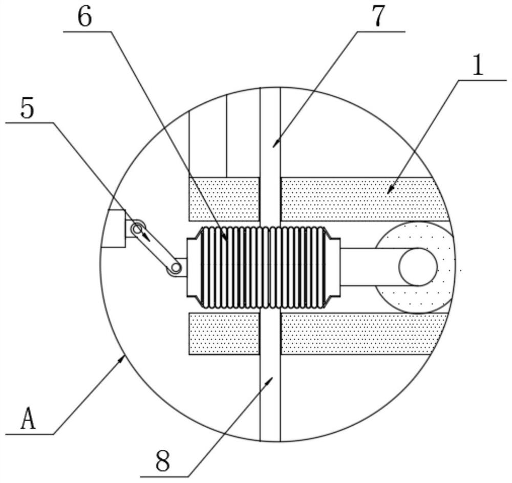
[0021] see Figure 1-5 , a fingerprint identification and time attendance device based on the Internet of Things, comprising a casing 1, the top casing 2 is fixedly connected to the left and right sides of the upper surface of the casing 1, the first airbag 6 is movably connected to the inside of the casing 1, and one end of the first airbag 6 The first connecting rod 5 is movably connected, and one end of the first connecting rod 5 is movably connected with t...


PUM


Abstract

The invention relates to the technical field of fingerprint identification, in particular to fingerprint identification attendance equipment based on the Internet of Things. Top shells are fixedly connected to the left side and the right side of the upper surface of an outer shell, a first air bag is movably connected into the outer shell, and a first connecting rod is movably connected to one endof the first air bag; a recording plate is movably connected to one end of the first connecting rod, a first pressing rod is fixedly connected to the top end of the first air bag and movably penetrates through the upper surface of the shell, and a second pressing rod is fixedly connected to the bottom end of the first air bag and movably penetrates through the interior of the shell; an air storage box is fixedly connected to the bottom end of the interior of the outer shell and located below the recording plate, the first air bag deforms and extrudes the first pressing rod to enable the firstpressing rod to move upwards, the first pressing rod moves upwards to extrude water in the water storage bag to be sprayed to the recording plate in a mist mode, the push plate also extrudes the water storage bag to spray water mist, and the effect of wetting dry fingers is achieved. The input of the fingerprint on the optical fingerprint identification equipment is facilitated.

Description

technical field [0001] The invention relates to the technical field of fingerprint identification, in particular to a fingerprint identification attendance device based on the Internet of Things. Background technique [0002] Fingerprint identification technology often appears in the access control and attendance functions of the one-card system. From the perspective of wide-area applications, the application direction of fingerprint identification technology includes four types. One is confidential systems, which require high security protection; The third is the citizen application for urban public affairs; the fourth is the authentication application that enters the virtual world of the Internet from real life. When employees check their attendance at work, they need to enter their fingerprints in advance and save them in the punch card machine. The identity can be identified by entering the same fingerprint again at the same time. [0003] Due to the limitations of the ...

Claims


Application Information

Patent Timeline
Patent Type & Authority Applications(China)
IPC IPC(8): G07C1/10G06K9/00F16H37/12
CPCG07C1/10F16H37/124G06V40/13
Inventor 刘鹏程
Owner 刘鹏程
Why Eureka
Try Eureka