
An energy router for distributed power station

A router and distributed technology, applied in the direction of panel/switch station circuit device, substation/switch layout details, substation/distribution device housing, etc. Internal conditions, shortening the service life of the device, etc., to avoid damage to the internal circuit and prevent normal use, avoid normal use, and ensure the effect of service life

Active Publication Date: 2022-07-01
HXXN ELECTRICITY
View PDF9 Cites 0 Cited by
  • Summary
  • Abstract
  • Description
  • Claims
  • Application Information

AI Technical Summary

Problems solved by technology

[0002] The energy router can realize the input, output, conversion, and storage of different energy carriers, realize the interconnection and complementarity of different energy forms, the organic connection between production and consumption, realize the integration of energy flows with different characteristics, and support the interconnection of wide-area energy networks; both It can be the energy production of large hydropower plants, wind farms, and photovoltaic power plants, or the energy production of parks, buildings, and users themselves. With the continuous development of society, energy routers are gradually playing an important role, but the energy of some distributed power plants When the router is used in harsh weather conditions, it cannot protect itself well, especially in colder and hotter weather, which affects the normal use of the device; In the case of water, the threat to the device caused by the rise of the liquid level cannot be well avoided, which will shorten the service life of the device, and when the device fails, it is not convenient to quickly observe the internal conditions of the device, so that it cannot be quickly specified maintenance program, reducing the maintenance efficiency of the device

Method used


Image

  • An energy router for distributed power station
  • An energy router for distributed power station
  • An energy router for distributed power station

Examples


Embodiment 1

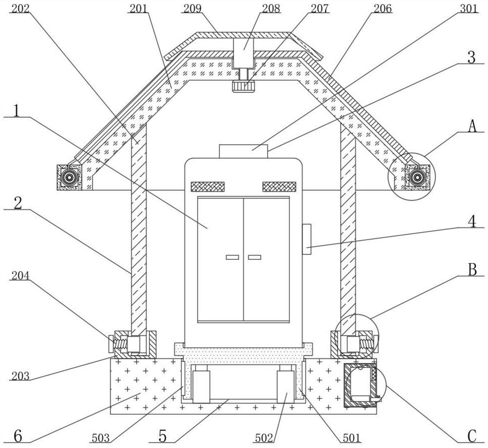
[0024] see figure 1 , figure 2 , image 3 , Figure 4 and Figure 5 , the present invention provides a kind of technical scheme:

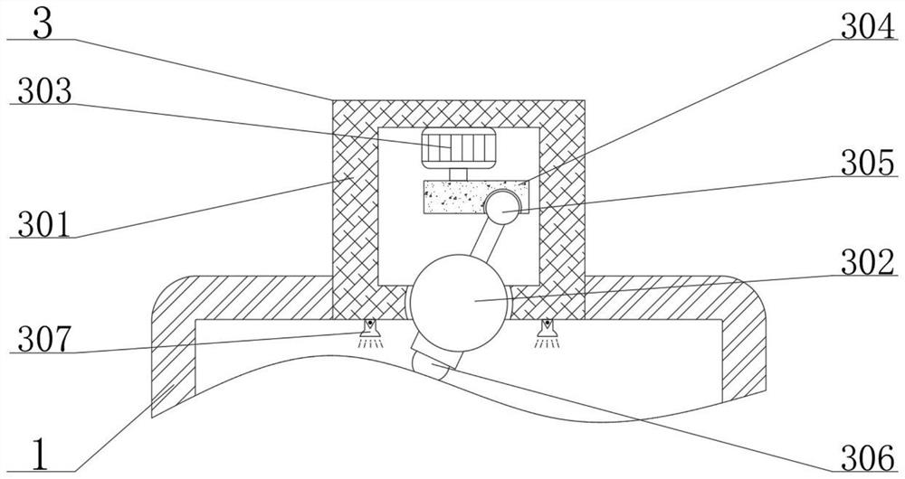
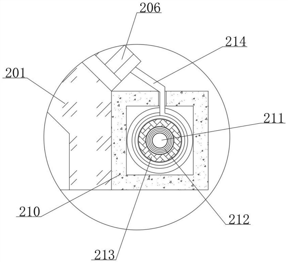
[0025] An energy router of a distributed power station includes a base 6, a protective device 2, a monitoring device 3 and a lifting device 5. The inner side of the base 6 is provided with a lifting device 5, and the lifting device 5 includes a support frame 501. The bottom end surface of the energy router 1 is slidably connected with a The support frame 501 is slidably connected to the base 6, the inner side of the support frame 501 is fixedly connected with a hydraulic rod 502, the outer side of the support frame 501 is fixedly connected with a sealing sleeve 503, and the sealing sleeve 503 is slidably connected to the base 6 up and down, the sealing sleeve 503 It is made of rubber material. When the support frame 501 moves up and down, it can prevent water from entering the base 6. A detection box 504 is fixedly connected to the right end o...

Embodiment 2

[0028] see figure 1 , figure 2 , image 3 , Figure 4 and Figure 5 , the present invention provides a kind of technical scheme:

[0029] An energy router of a distributed power station includes a base 6, a protective device 2, a monitoring device 3 and a lifting device 5. The inner side of the base 6 is provided with a lifting device 5, and the lifting device 5 includes a support frame 501. The bottom end surface of the energy router 1 is slidably connected with a The support frame 501 is slidably connected with the base 6, the inner side of the support frame 501 is fixedly connected with a hydraulic rod 502, the outer side of the support frame 501 is fixedly connected with a sealing sleeve 503, and the sealing sleeve 503 is slidably connected with the base 6, and the sealing sleeve 503 is It is made of a rubber material plate. When the support frame 501 moves up and down, it can prevent water from entering the base 6. A detection box 504 is fixedly connected to the righ...


PUM


Abstract

The invention relates to the technical field of energy routers, in particular to an energy router of a distributed power station, comprising a base, a protection device, a monitoring device and a lifting device, wherein a lifting device is arranged inside the base, A support frame is slidably connected to the bottom end face of the energy router, and the support frame is slidably connected to the base. A hydraulic rod is fixedly connected to the inner side of the support frame, and the hydraulic rod is fixedly connected to the base. The top of the lifting device is provided with an energy router. , Through the set of protective frame, this setting cooperates with the fixed connection between the protective frame and the fixing rod, the rotational connection between the threaded shaft and the clamping block, and the sliding connection between the clamping block and the limit block and the fixing rod, and is used in colder weather in winter. When the device is installed, it plays the role of blocking snow and rain, so as to protect the device well, and will not affect the irradiation of light to the device, and avoid the phenomenon that the device cannot be used normally due to low temperature.

Description

technical field [0001] The invention relates to the technical field of energy routers, in particular to an energy router of a distributed power station. Background technique [0002] The energy router can realize the input, output, conversion and storage of different energy carriers, realize the interconnection and complementation of different energy forms, the organic connection of production and consumption links, realize the integration of energy flows with different characteristics, and can support the interconnection of wide-area energy networks; both It can be the energy production of large hydropower plants, wind farms, photovoltaic power plants, or the energy production of parks, buildings, and users themselves. With the continuous development of society, energy routers gradually play an important role, but the energy of some distributed power plants When the router is used in harsh weather conditions, it cannot well protect itself, especially in colder and hotter we...

Claims


Application Information

Patent Timeline
Patent Type & Authority Patents(China)
IPC IPC(8): H02B1/26H02B1/28H02B1/50H02B1/24F16M11/06F16M11/18F16M11/14
CPCH02B1/26H02B1/28H02B1/505H02B1/24F16M11/06F16M11/18F16M11/14
Inventor 周斌张宽李文芳黎灿兵游玫瑰李佳勇
Owner HXXN ELECTRICITY
Learn More