
Power distribution cabinet with safety protection function

A technology for safety protection and power distribution cabinets, applied in substation/distribution device casings, electrical components, substation/switch layout details, etc. Efficiency, the effect of automatic control improvement

Inactive Publication Date: 2020-12-04
刘锦刚
View PDF0 Cites 2 Cited by
  • Summary
  • Abstract
  • Description
  • Claims
  • Application Information

AI Technical Summary

Problems solved by technology

[0002] The power distribution cabinet is the final equipment of the power distribution system. There are a large number of components distributed in the power distribution cabinet. A large number of components will generate a lot of heat when they work at the same time, which will cause the temperature in the power distribution cabinet to rise, and the temperature in the power distribution cabinet is too high. , Short circuit in the line or excessive dust is very easy to cause fire. If the fire cannot be extinguished in time, it will consume a lot of manpower and material resources and even endanger personal safety. In addition, the traditional power distribution cabinet has problems of poor heat dissipation and high energy consumption. In view of this, A power distribution cabinet with automatic fire extinguishing, dust removal and good heat dissipation is needed to extinguish the open flame in time to prevent the occurrence of fire

Method used


Image

  • Power distribution cabinet with safety protection function
  • Power distribution cabinet with safety protection function
  • Power distribution cabinet with safety protection function

Examples


Embodiment 1

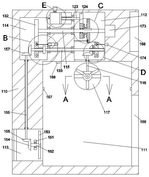
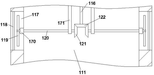
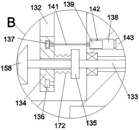
[0030] The rotation of the third rotating shaft 115 is controlled by the drive motor 173, and then the third rotating shaft 115 drives the first gear 132 to rotate. At this time, the third gear 134 and the fourth rotating shaft 133 are driven by the first gear 132 to rotate. At the same time, the fourth rotating shaft The third bevel gear 158 on the left side of 133 drives the sixth bevel gear 157 and the seventh bevel gear 156 at the bottom of the sixth rotating shaft 155 to rotate, thereby realizing the rotation of the seventh bevel gear 156 and the first fan blade 153 to realize the air intake 113 At the same time, because the second bayonet turntable 144 is connected with the second bayonet ring block 149, at this time, the second bayonet ring 144 drives the second bayonet ring block 149 and the fourth bevel gear 148 At the same time, the fourth bevel gear 148 drives the fifth bevel gear 150, the sixth bevel gear 122 and the second bevel gear 121 at the bottom of the fifth ...

Embodiment 2

[0032] The telescopic rod 147 is controlled by the telescopic controller 174 to drive the second bayonet turntable 144 away from the second bayonet ring block 149, so that the driving motor 173 controls the rotation of the third rotating shaft 115, and then the third rotating shaft 115 drives the first gear 132 to rotate. At this time, the third gear 134 and the fourth rotating shaft 133 are driven by the first gear 132 to rotate, and at the same time, the third bevel gear 158 on the left side of the fourth rotating shaft 133 drives the sixth bevel gear 157 and the seventh bevel gear at the bottom of the sixth rotating shaft 155. The bevel gear 156 rotates to drive the seventh bevel gear 156 and the first fan blade 153 to rotate to realize the air intake control work of the air inlet 113. At this time, the second fan blade 119 is in a static state to realize the air outlet 117. Normal exhaust work, reduce energy consumption;

Embodiment 3

[0034] When a fire broke out in the equipment cavity 111, at this moment, the fire detection sensor 166 sends a signal and controls the electromagnetic coil device 143 to open, so that the magnetic movable block 139 and the electromagnetic coil device 143 generate suction and move to the right, and then the magnetic movable block 139 The third gear 134 is driven by the first pull cord 141 to overcome the top pressure of the second spring 172 and stay away from the first gear 132. At the same time, the magnetic movable block 139 drives the first latch turntable 128 to overcome the first spring 131 through the second pull cord 142. The top pressure is connected with the ring block 127 of the first slot, and then the third rotating shaft 115 is controlled by the drive motor 173 to rotate, and the ring block 127 of the first slot and the second gear 125 are driven by the first tooth turntable 128 to rotate. , the second gear 125 drives the fourth gear 124 and the push screw 123 to ...


PUM


Abstract

A power distribution cabinet with a safety protection function disclosed by the present invention comprises a main cabinet body, an equipment cavity is arranged in the main cabinet body, an air inletcommunicated with the outside is arranged in the left side wall of the equipment cavity, air outlets communicated with the outside are symmetrically arranged in the front wall and the rear wall of theequipment cavity, and a first driving cavity is arranged on the upper side of the equipment cavity, a second driving cavity is formed in the left side of the first driving cavity, a driving mechanismis arranged in the first driving cavity, a linkage mechanism connected with the driving mechanism in a matched mode is arranged in the second driving cavity, dustproof plates are arranged in the airinlet and the air outlet, and a first supporting plate extending front and back is further fixedly arranged in the air inlet; a first rotating shaft is connected into the first supporting plate in a rotating fit mode, a first bevel gear is fixedly arranged in the left side of the first rotating shaft, first fan blades are fixedly arranged at the right end of the first rotating shaft, a second supporting plate is further fixedly arranged in the air outlet, a second rotating shaft is connected into the second supporting plate in a rotating fit mode, and a second fan blade is fixedly arranged atthe side, far away from the equipment cavity, of the second rotating shaft.

Description

technical field [0001] The invention relates to the technical field of power distribution cabinets, in particular to a power distribution cabinet with a safety protection function. Background technique [0002] The power distribution cabinet is the final equipment of the power distribution system. There are a large number of components distributed in the power distribution cabinet. A large number of components will generate a lot of heat when they work at the same time, which will increase the temperature in the power distribution cabinet and the temperature in the power distribution cabinet will be too high. , Short circuit in the line or excessive dust is very easy to cause fire. If the fire cannot be extinguished in time, it will consume a lot of manpower and material resources and even endanger personal safety. In addition, the traditional power distribution cabinet has problems of poor heat dissipation and high energy consumption. In view of this, There is a need for a ...

Claims


Application Information

Patent Timeline
Patent Type & Authority Applications(China)
IPC IPC(8): H02B1/30H02B1/28H02B1/56A62C3/16A62C31/02
CPCA62C3/16A62C31/02H02B1/28H02B1/30H02B1/565
Inventor 刘锦刚
Owner 刘锦刚
Learn More