
Portable mobile power supply

A mobile power supply, portable technology, applied in the direction of current collectors, electric vehicles, electrical components, etc., can solve the problems of no support device, inconvenient, no handle or pull rod, etc., to avoid taking up too much space and easy to carry or handling, shortening the service life

Inactive Publication Date: 2020-12-04
湖南衡盈电子科技有限公司
View PDF4 Cites 0 Cited by
  • Summary
  • Abstract
  • Description
  • Claims
  • Application Information

AI Technical Summary

Problems solved by technology

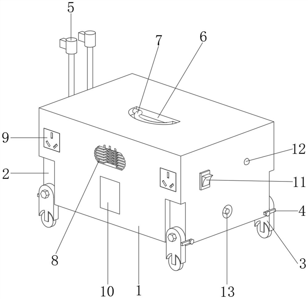
[0003] The existing outdoor mobile power supply has the following disadvantages when working: 1. The existing outdoor mobile power supply is usually set in a box structure without a handle or a pull rod. When moving, it can only be lifted by both hands, which is very inconvenient. There is a lack of an outdoor mobile power supply that can be lifted by the handle and pushed and pulled by the push rod; 2. The existing outdoor mobile power supply is usually not provided with a support device, and it is placed directly on the ground outdoors when in use, which may cause damage to the power supply. Wet electronic devices will affect the normal use of the mobile power supply and shorten the service life of the mobile power supply

Method used


Image

  • Portable mobile power supply
  • Portable mobile power supply
  • Portable mobile power supply

Examples


Embodiment Construction

[0020] In order to make the technical means, creative features, goals and effects achieved by the present invention easy to understand, the present invention will be further described below in conjunction with specific embodiments.

[0021] In the description of the present invention, it should be noted that the terms "upper", "lower", "inner", "outer", "front end", "rear end", "both ends", "one end", "another end" The orientation or positional relationship indicated by etc. is based on the orientation or positional relationship shown in the drawings, and is only for the convenience of describing the present invention and simplifying the description, rather than indicating or implying that the referred device or element must have a specific orientation, use a specific Azimuth configuration and operation, therefore, should not be construed as limiting the invention. In addition, the terms "first" and "second" are used for descriptive purposes only, and should not be understood ...


PUM


Abstract

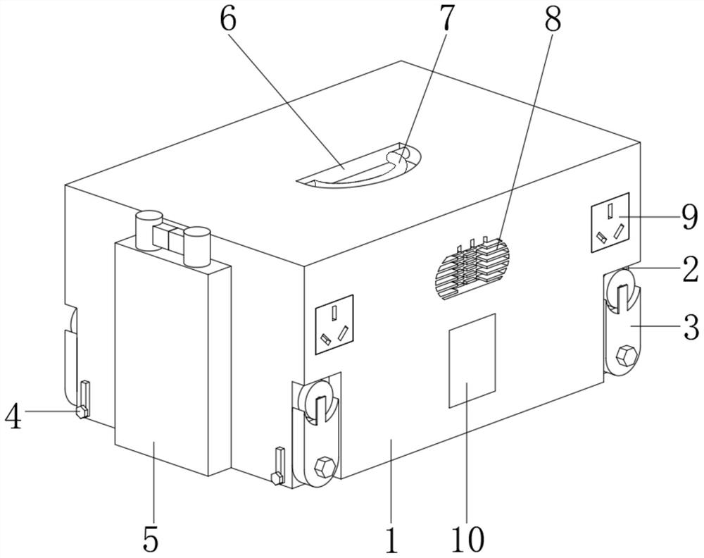
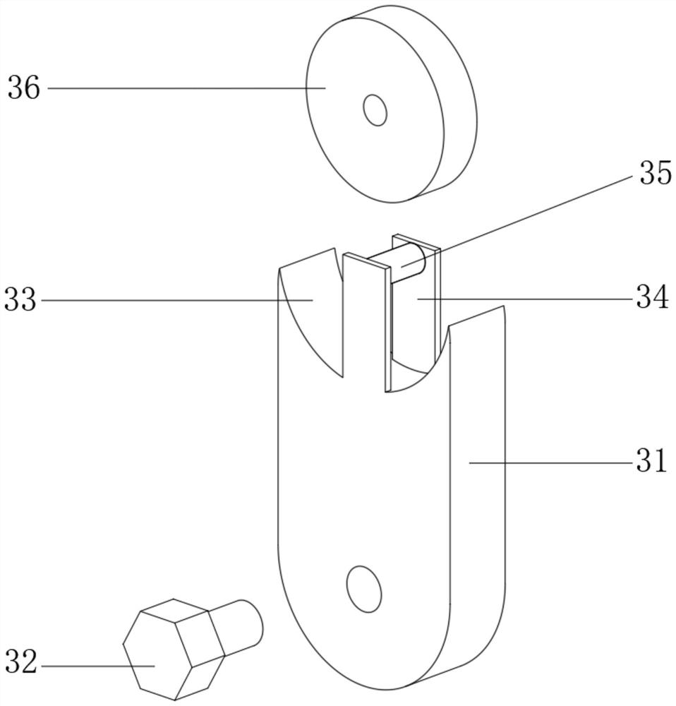
The invention discloses a portable mobile power supply, which comprises a power supply body, wherein supporting grooves are formed in the lower left portion of the front end, the lower right portion of the front end, the lower left portion of the rear end and the lower right portion of the rear end of the power supply body, supporting devices are arranged in the four supporting grooves, the left lower portion, the left lower portion, the right lower portion, the right lower portion and the right lower portion of the left end of the power source body are each rotationally connected with a movable stop rod, a push-pull device is arranged at the left end of the power source body, a handle groove is formed in the middle of the upper end of the power source body, a movable handle is rotationally connected between the left groove wall and the right groove wall of the handle groove. heat dissipation holes are formed in the upper portion of the front end of the power source body, jacks are formed in the left portion and the right portion of the front end of the power source body, a switch is fixedly installed on the front portion of the right end of the power source body, and a charging port is fixedly installed on the lower portion of the right end of the power source body. The portable mobile power supply provided by the invention is convenient to carry and transport, and can preventequipment from being affected with damp and short-circuited due to damp ground.

Description

technical field [0001] The invention relates to the technical field of mobile power supplies, in particular to a portable mobile power supply. Background technique [0002] With the development of the economy and the improvement of living standards, outdoor work is getting higher and higher. When performing outdoor work, power supply equipment is often required for power supply. Most of the outdoor mobile power supplies are equipped with ion battery packs to store electrical energy. [0003] The existing outdoor mobile power supply has the following disadvantages when working: 1. The existing outdoor mobile power supply is usually set in a box structure without a handle or a pull rod. When moving, it can only be lifted by both hands, which is very inconvenient. There is a lack of an outdoor mobile power supply that can be lifted by the handle and pushed and pulled by the push rod; 2. The existing outdoor mobile power supply is usually not provided with a support device, and ...

Claims


Application Information

Patent Timeline
Patent Type & Authority Applications(China)
IPC IPC(8): H02J7/00
CPCH02J7/0042H02J7/0044
Inventor 崔长印
Owner 湖南衡盈电子科技有限公司
Learn More