
Wireless communication system device for communication

A wireless communication system and line-through technology, applied in the transmission system, coupling device, selection device, etc., can solve the problems of reducing the use effect of the device, the device is easy to shake, and the device is damaged, so as to prevent the temperature from being too high, increase the use effect, The effect of preventing left and right shaking

Inactive Publication Date: 2020-12-04
广州融益科技有限公司
View PDF0 Cites 3 Cited by
  • Summary
  • Abstract
  • Description
  • Claims
  • Application Information

AI Technical Summary

Problems solved by technology

[0004] Aiming at the deficiencies of the prior art, the present invention provides a wireless communication system device for communication, which solves the problem that the wireless communication system device for communication currently used does not have the effect of heat dissipation. When the internal temperature of the device is too high, it may The internal parts are damaged, and there is no protective effect. The device is easily damaged by external factors, and it does not have the function of fixing. The device is easy to shake during transportation, causing damage to the device, and does not have effective The effect of shock absorption, when the device falls from a high place, it is easy to cause damage to the device, thereby greatly reducing the use effect of the device

Method used


Image

  • Wireless communication system device for communication
  • Wireless communication system device for communication
  • Wireless communication system device for communication

Examples


Embodiment

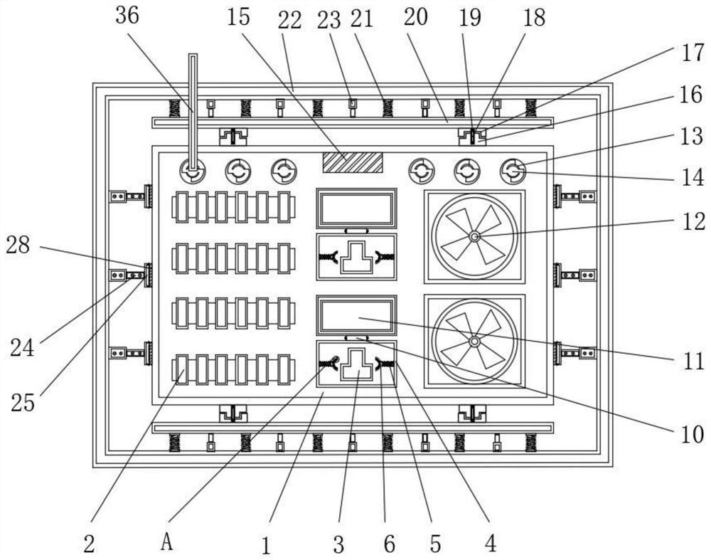
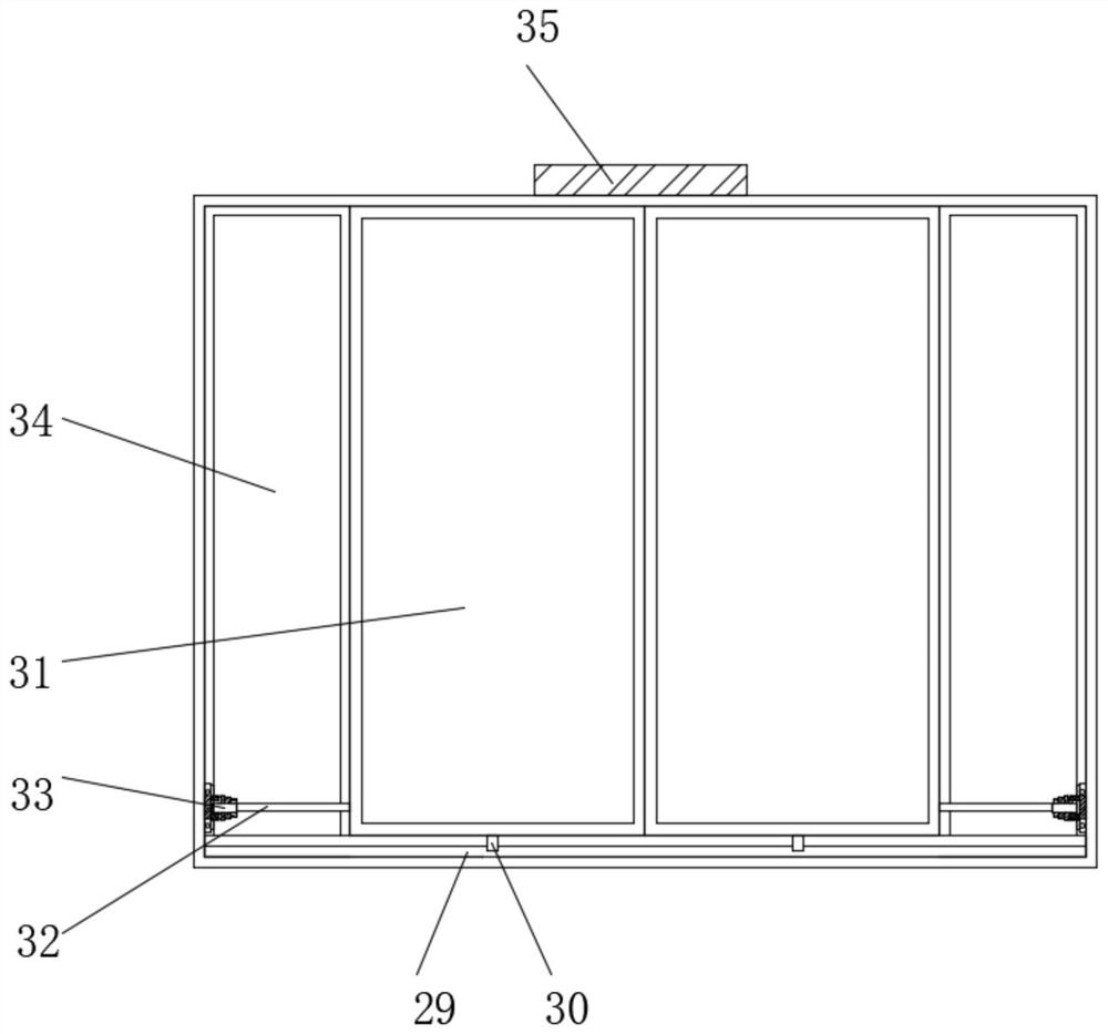
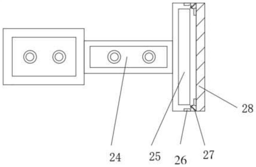
[0038] see Figure 1-7 , in this embodiment: a wireless communication system device for communication, including a router 1, a wire slot 3, a fan 12, a limit block 13, a thermal sensor 15, a support plate 20, a lifting rod 24, a chute 29, an ultraviolet light The sensor 35 and the antenna 36, ​​the outer wall of the router 1 are all provided with cooling fins 2, and the wire slot 3 is arranged on the outer wall of the router 1, and the outer side of the wire slot 3 is provided with a first protective shell 4, and the inner wall of the first protective shell 4 is provided with a telescopic Bar 5, and the first fixed plate 6 is arranged on one side of the telescopic bar 5, and the first movable block 7 is arranged inside the first fixed plate 6, and the first hook 8 is arranged on the inner side of the first movable block 7, and the first hook 8 is provided with a first rubber cushion 9 on one side, a rotating bolt 10 is arranged above the first protective shell 4, and a protect...


PUM


Abstract

The invention belongs to the related technical field of communication, and particularly relates to a wireless communication system device for communication, which comprises a router, wire passing grooves, fans, limiting blocks, a thermal inductor, a supporting plate, a lifting rod, a sliding groove, an ultraviolet sensor and an antenna. The outer wall of the router is provided with cooling fins, and the wire passing grooves are formed in the outer wall of the router; and a first protective shell is arranged on the outer side of each wire passing groove, telescopic strips are arranged on innerwalls of each first protective shell, a first fixed plate is arranged on one side of each telescopic strip, first movable blocks are arranged in each first fixed plate, first hooks are arranged on theinner sides of the first movable blocks, and meanwhile first rubber cushions are arranged on one sides of the first hooks. According to the wireless communication system device for communication, through the arrangement of the springs, the telescopic rods and the supporting plates, a damping and buffering effect can be achieved on the device, the situation that a router is broken when the devicefalls from a high position is prevented, and therefore the using effect of the device is greatly improved.

Description

technical field [0001] The present invention relates to the related technical field of wireless communication, in particular to a wireless communication system device for communication. Background technique [0002] Wireless communication refers to long-distance transmission and communication between multiple nodes without transmission through conductors or cables. Wireless communication can be performed using radios, radios, etc. Wireless communication includes various fixed, mobile and portable applications, such as two-way radio , mobile phones, personal digital assistants, and wireless networks. Examples of other radio wireless communications include GPS, garage door remote controls, and wireless mice. Most wireless communication technologies use radio, including Wi-fi, which is only a few meters away. It also includes the deep space network that communicates with Voyager 1 and has a distance of more than millions of kilometers. However, some wireless communication techn...

Claims


Application Information

Patent Timeline
IPC IPC(8): H04L12/771H04Q1/02H04Q1/04H01R13/52H04L45/60
CPCH04L45/60H04Q1/112H04Q1/02H04Q1/035H04Q1/11H04Q1/04H01R13/5213
Inventor 沈子文
Owner 广州融益科技有限公司
Learn More