Direct-current power supply lighting dimming module

A dimming module, DC power supply technology, applied in the direction of electrical components, etc.

Pending Publication Date: 2020-12-04
深圳市英可瑞直流技术有限公司
View PDF0 Cites 1 Cited by
  • Summary
  • Abstract
  • Description
  • Claims
  • Application Information

AI Technical Summary

Problems solved by technology

[0002] The DC centralized lighting technology is to centrally place the distributed AC / DC rectifiers in the traditional LED lamp driver in the power supply cabinet, and use the voltage low-frequency rise and fall of high-voltage direct current to couple the dimming information, and transmit it to the decoding chip on the lamp driver for adjustment. A new type of dimming technology for light; the specific application method of DC centralized lighting technology is: low-voltage alternating current enters the power distribution cabinet, is transformed into 200V-300V DC by a rectifier module, and is output from the power distribution cabinet to the outside of the power distribution cabinet through multiple cables. However, the current industrialization of DC centralized lighting technology faces a pain point: the lack of a device that can quickly adjust the brightness of a lamp in a certain loop of the DC lighting power supply system

Method used


Image

  • Direct-current power supply lighting dimming module
  • Direct-current power supply lighting dimming module
  • Direct-current power supply lighting dimming module

Examples


Embodiment 1

[0032] Please refer to Figure 1 to Figure 10 , Embodiment 1 of the present invention is:

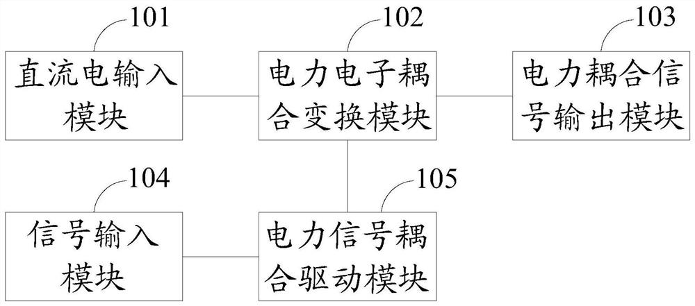
[0033] Please refer to figure 1 , a DC power supply lighting dimming module, including a DC input module 101, a power electronics coupling transformation module 102, a power coupling signal output module 103, a signal input module 104 and a power signal coupling driving module 105, the power electronics coupling transformation module 102 They are respectively electrically connected to the DC input module 101, the power coupling signal output module 103 and the power signal coupling driving module 105, the signal input module 104 is electrically connected to the power signal coupling driving module 105, and the power coupling signal output module 103 is connected to the peripheral The lamps 5 are electrically connected.

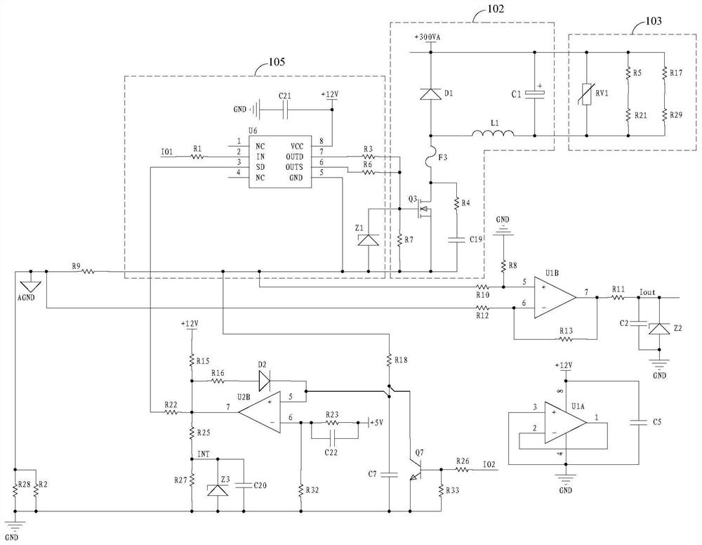
[0034] Please refer to figure 2 The power electronic coupling conversion module 102 includes a resistor R4 (resistance value is 100Ω), a resistor R7 (resistance val...

Embodiment 2

[0060] Please refer to Figure 11 , the second embodiment of the present invention is:

[0061] The difference between the second embodiment and the first embodiment is that the BOOST topology of the power electronics coupling conversion module 102 includes a filter capacitor C201, a reactor L201, a resistor R201, a dummy load Rf2, a diode D201 and a field effect transistor Q201. The gate of the effect transistor Q201 is electrically connected to the power coupling signal driving module, the drain of the field effect transistor Q201 is electrically connected to one end of the reactor L201 and the anode of the diode D201 respectively, and the source of the field effect transistor Q201 is respectively connected to One end of the resistor R201 is electrically connected to one end of the dummy load Rf2, the cathode of the diode D201 is electrically connected to one end of the filter capacitor C201 and the other end of the dummy load Rf2, and the other end of the filter capacitor C...


PUM


Abstract

The invention relates to the technical field of direct-current power supply lighting, in particular to a direct-current power supply lighting dimming module, which comprises a direct-current input module, a power electronic coupling conversion module, a power coupling signal output module, a signal input module and a power signal coupling driving module. The power electronic coupling conversion module is electrically connected with the direct current input module, the power coupling signal output module and the power signal coupling driving module, and the signal input module is electrically connected with the power signal coupling driving module. After the direct current is inputted to the dimming, a power coupling signal with a coupling signal is obtained through conversion through the power electronic coupling conversion module, and is output to a lamp through the power coupling signal output module; a dimming signal is recognized and converted into a driving signal through the power signal coupling driving module, and the power electronic coupling conversion module sends out a low-frequency high voltage and a low voltage with the amplitude of + / - 5V, so that the brightness of alamp of a certain loop of the direct-current lighting power supply system is adjusted.

Description

technical field [0001] The invention relates to the technical field of DC power supply lighting, in particular to a DC power supply lighting dimming module. Background technique [0002] The DC centralized lighting technology is to centrally place the distributed AC / DC rectifiers in the traditional LED lamp driver in the power supply cabinet, and use the voltage low-frequency rise and fall of high-voltage direct current to couple the dimming information, and transmit it to the decoding chip on the lamp driver for adjustment. A new type of dimming technology for light; the specific application method of DC centralized lighting technology is: low-voltage alternating current enters the power distribution cabinet, is transformed into 200V-300V DC by a rectifier module, and is output from the power distribution cabinet to the outside of the power distribution cabinet through multiple cables. However, the current industrialization of DC centralized lighting technology faces a pain...

Claims


Application Information

Patent Timeline
Patent Type & Authority Applications(China)
IPC IPC(8): H05B45/14
CPCH05B45/14
Inventor 廖闻迪商洪亮江钦彬王国求
Owner 深圳市英可瑞直流技术有限公司
Why Eureka
Try Eureka