Concealed charging small door

An inner hidden and concealed technology, which is applied in the field of inner hidden charging small doors, can solve problems such as safety accidents and affecting visual appearance, and achieve the effects of improving safety, good appearance, and accurate opening and closing actions

Pending Publication Date: 2020-12-08
宁波百德汽车饰件有限公司
View PDF0 Cites 2 Cited by
  • Summary
  • Abstract
  • Description
  • Claims
  • Application Information

AI Technical Summary

Problems solved by technology

Naughty children are curious about the fact that the flipped cover plate can be flipped during the charging process, which is prone to safety accidents; i

Method used


Image

  • Concealed charging small door
  • Concealed charging small door
  • Concealed charging small door

Examples


Embodiment 1

[0040] refer to Figure 1 to Figure 10 , a built-in hidden charging small door, comprising:

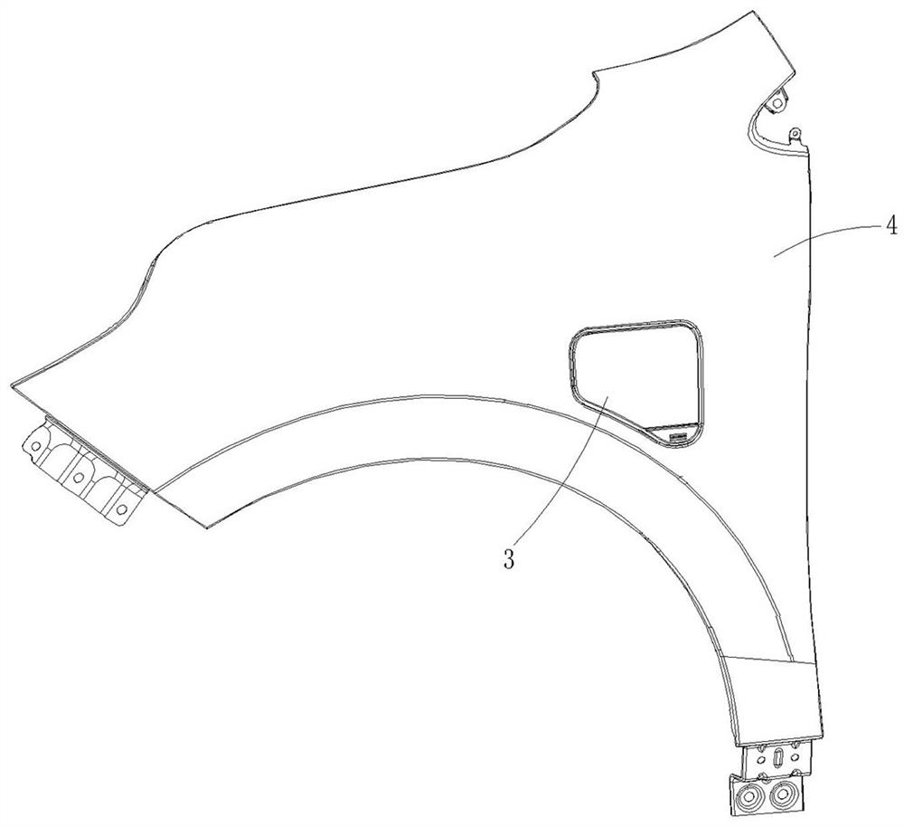
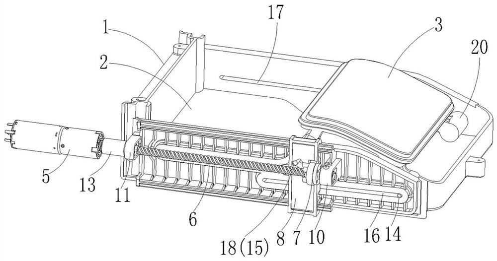
[0041] The charging port seat 1 has an inner cavity 2, an external opening 29 communicating with the inner cavity 2, and a charging interface respectively communicating with the inner cavity 2 and the battery assembly in the vehicle, and the charging port seat 1 is also provided with a guide track groove;

[0042] The charging port cover 3 is installed in the charging port seat 1 in an openable and closable manner, and has at least a closed state and an open and hidden state. The charging port cover 3 is provided with a sliding foot assembly, and the sliding foot assembly is slid In the guide track groove;

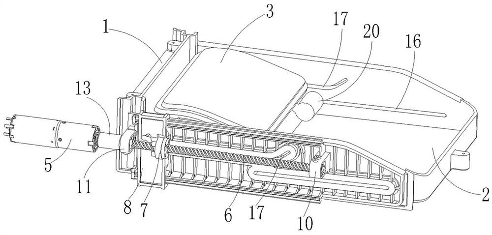
[0043] The driving mechanism 5 is used to provide power to switch the charging port cover 3 between the closed state and the open and hidden state;

[0044] Lead screw slider transmission assembly, which includes a lead screw 6, a nut seat 7 and a guide slider 8 connected in seq...

Embodiment 2

[0053] refer to Figure 11 The difference between the present embodiment and the first embodiment is only that: the upper and lower ends of the guide slider 8 are provided with a connecting portion 26 protruding inward, and the connecting portion 26 is provided with a slideway groove 27, so The upper and lower ends of the outer wall of the charging port seat 1 are provided with guide sliders 28, and the guide sliders 28 are embedded in the slideway grooves 27, so that the guide slider 8 can move along the The guide slide bar 28 slides back and forth. Adopting the structural arrangement of this embodiment, a more reliable cooperative relationship is formed between the guide slider 8 and the charging port cover 3, and the sliding operation of the guide slider 8 is more stable and reliable, and no jamming or derailment occurs .

[0054] When the present invention is applied in the automobile, its working principle is as follows:

[0055] When the charging port cover 3 needs to...


PUM


Abstract

A concealed charging small door comprises a charging port base, a charging port cover, a driving mechanism and a lead screw and sliding block transmission assembly. The charging port base is providedwith an inner cavity, an external opening communicated with the inner cavity and a charging interface respectively communicated with the inner cavity and a battery assembly in a vehicle, and a guide track groove is further formed in the charging port base. The charging port cover is installed in the charging port base in an openable and closable mode and at least has a closed state and an open hidden state, the charging port cover is provided with a sliding foot assembly, and the sliding foot assembly is arranged in the guide track groove in a sliding mode. The driving mechanism is used for providing power so as to switch the charging port cover between a covering state and an opening hidden state. The lead screw and sliding block transmission assembly comprises a lead screw, a nut seat and a guide sliding block which are sequentially connected, the lead screw is in transmission connection with the driving mechanism, and the guide sliding block is in transmission connection with the sliding foot assembly. The charging port cover has a closed state and an open hidden state, the occupied space is reduced, the production cost is reduced, and better safety, reliability and attractiveness can be achieved concurrently in the using process.

Description

technical field [0001] The invention relates to the technical field of charging equipment, in particular to a built-in hidden charging door applied to new energy electric vehicles. Background technique [0002] New energy electric vehicles refer to vehicles powered by vehicle-mounted power supplies and driven by motors to drive wheels, which meet the requirements of road traffic and safety regulations. It uses electricity stored in the battery to start. Sometimes 12 or 24 batteries are used to power the car, sometimes more. This type of car is generally provided with a charging port cover on the body, and the charging port cover can open or close the charging port, and the charging gun rushes through the charging port to charge the battery in the car. Specifically, the charging door is used to close or open the charging port in the body of the vehicle with the electric drive, the charging door has a charging cover, and the charging cover can move between a closed position ...

Claims


Application Information

Patent Timeline
IPC IPC(8): B62D25/24B60L53/16E05F15/652E05F15/655
CPCB62D25/24B60L53/16E05Y2900/53E05F15/652E05F15/655Y02T10/70Y02T10/7072Y02T90/14
Inventor 周利怀杨幸辉
Owner 宁波百德汽车饰件有限公司
Why Eureka
Try Eureka