
Pressure gauge with peripheral transparent protection structure

A technology for transparent protection and pressure gauges, applied in the direction of measuring fluid pressure, measuring devices, instruments, etc., can solve the problems of pressure gauge breakage and falling, poor stability and reliability, and limited protection, so as to avoid damage and facilitate disassembly Decoration and design humanized effect

Active Publication Date: 2020-12-08
安徽瑞尔特仪表科技有限公司
View PDF16 Cites 1 Cited by
  • Summary
  • Abstract
  • Description
  • Claims
  • Application Information

AI Technical Summary

Problems solved by technology

[0003] Existing pressure gauges are generally connected to pipelines in two ways, namely threaded connection and flange connection. The threaded connection is screwed into the threaded hole on the pipe wall through the threaded end on the joint; the existing pressure gauge is in use However, there are the following disadvantages: on the one hand, the dial of the existing pressure gauge is only protected by the set glass panel, but the glass panel is fragile, and the protective effect is limited, and the broken glass panel will affect the pressure gauge. Accuracy, the pressure gauge needs to be replaced, which is inconvenient; on the other hand, the pressure gauge is only connected to the pipe wall through the threaded end, and the stability and reliability of the connection are poor. When the pressure gauge is subjected to external forces such as collisions, The pressure gauge is very easy to break and fall due to impact; in view of this, we propose a pressure gauge with a transparent protective structure around it

Method used


Image

  • Pressure gauge with peripheral transparent protection structure
  • Pressure gauge with peripheral transparent protection structure
  • Pressure gauge with peripheral transparent protection structure

Examples


Embodiment Construction

[0037] The following will clearly and completely describe the technical solutions in the embodiments of the present invention with reference to the accompanying drawings in the embodiments of the present invention. Obviously, the described embodiments are only some, not all, embodiments of the present invention. Based on the embodiments of the present invention, all other embodiments obtained by persons of ordinary skill in the art without making creative efforts belong to the protection scope of the present invention.

[0038] In describing the present invention, it should be understood that the terms "center", "longitudinal", "transverse", "length", "width", "thickness", "upper", "lower", "front", " Orientation indicated by rear, left, right, vertical, horizontal, top, bottom, inside, outside, clockwise, counterclockwise, etc. The positional relationship is based on the orientation or positional relationship shown in the drawings, which is only for the convenience of describ...


PUM

PropertyMeasurementUnit
heightaaaaaaaaaa

Abstract

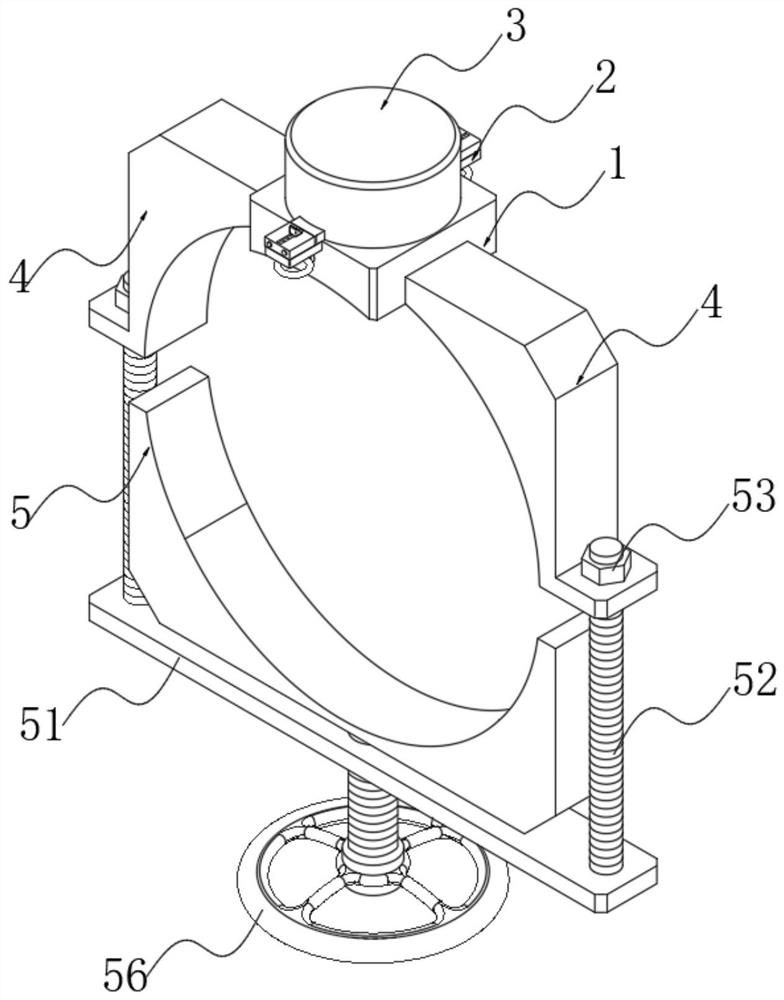
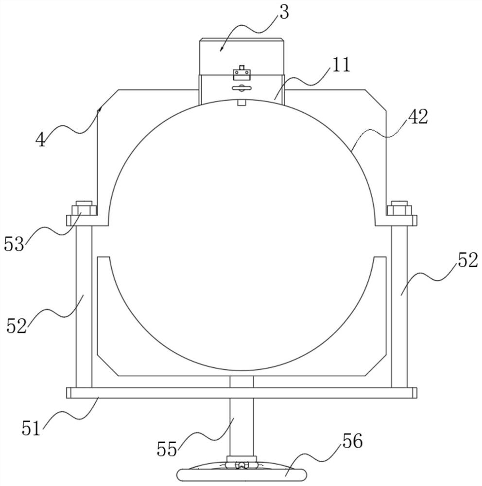
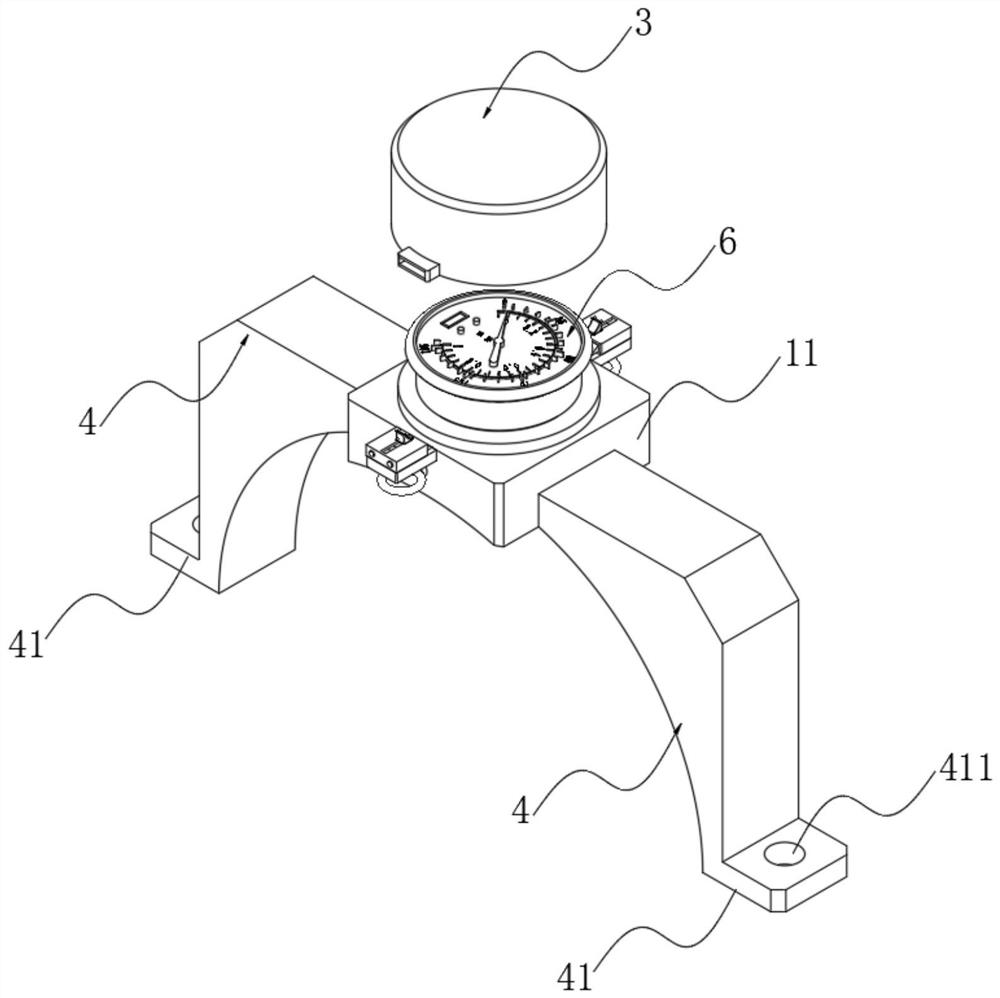
The invention relates to the technical field of pressure gauges, in particular to a pressure gauge with a peripheral transparent protection structure, which comprises a pressure gauge fixing mechanism, and is characterized in that a shield fixing mechanism is arranged on the pressure gauge fixing mechanism; according to the pressure gauge with the peripheral transparent protective structure, the protective cover fixing mechanism and the transparent protective cover are arranged, so that the protective cover is convenient to disassemble and assemble, and the protective cover is convenient to maintain or replace; the transparent protective cover does not influence the reading of the dial plate, so that the design is humanized; according to the pressure gauge with the peripheral transparent protection structure, the pressure gauge fixing mechanism and the connecting mechanism are arranged, so that the connecting stability and firmness of the pressure gauge and a pipeline are improved; according to the pressure gauge, the fixing mode of a traditional pressure gauge is changed, the pressure gauge is stably fixed to a pipeline through a series of structures on the pressure gauge, damageto the pressure gauge due to external force impact and the like is avoided, and the pressure gauge is protected.

Description

technical field [0001] The invention relates to the technical field of pressure gauges, in particular to a pressure gauge with a peripheral transparent protective structure. Background technique [0002] A pressure gauge is an instrument that uses elastic elements as sensitive elements to measure and indicate pressure higher than the environment. It is widely used, and it pervades almost all industrial processes and scientific research fields. It can be seen everywhere in heat pipe network, oil and gas transmission, water supply and gas supply system, vehicle repair and maintenance factory and shop. Especially in the process of industrial process control and technical measurement, due to the high mechanical strength and convenient production of the elastic sensitive components of mechanical pressure gauges, mechanical pressure gauges are more and more widely used; pressure gauges are composed of pointers, Composed of glass panels and overflow holes, etc.; there are many typ...

Claims


Application Information

Patent Timeline
Patent Type & Authority Applications(China)
IPC IPC(8): G01L19/06G01L19/14G01L19/00
CPCG01L19/0654G01L19/144G01L19/00
Inventor 马玉辉
Owner 安徽瑞尔特仪表科技有限公司
Learn More