
Novel differential InSAR LOS direction deformation quantity estimation method

A technology of deformation and difference, which is applied in the field of surveying and remote sensing radar, can solve the problems of high cost, long re-measurement time interval, and inability to guarantee the accuracy and timeliness of monitoring data, etc., to achieve a more accurate and uniform deformation distribution Effect

Pending Publication Date: 2020-12-08
中冶(北京)交通科技发展有限公司 +1
View PDF0 Cites 12 Cited by
  • Summary
  • Abstract
  • Description
  • Claims
  • Application Information

AI Technical Summary

Problems solved by technology

[0002] Most of the existing monitoring methods are to install a variety of sensors on the ground for monitoring, vertical inclination holes, external deformation observation piers, vertical displacement, measuring points, multi-point displacement meters, GNSS, anchor cable dynamometers, anchor cable dynamometers , anchor tendon dynamometer, osmometer, etc. The measurement content is mostly internal deformation monitoring of the cracked body, external deformation monitoring, seepage pressure and support body stress monitoring, etc. The advantages of these methods are high measurement accuracy and reliable results. The disadvantages are that it consumes a lot of manpower and material resources, high cost, sparse measurement points, and long re-measurement intervals. The safety of monitoring personnel cannot be effectively guaranteed, the monitoring range is small, and it is greatly affected by the environment. There is a large flow of personnel and uneven professional quality. Working in remote mountainous areas all year round, employees tend to have strong inertia and fluke thinking, weak safety awareness, difficult measurement, and serious human factors. The accuracy and timeliness of monitoring data cannot be guaranteed. Existing monitoring technical means cannot satisfy large-scale and high-frequency monitoring, and it is urgent to find new technical means

Method used


Image

  • Novel differential InSAR LOS direction deformation quantity estimation method
  • Novel differential InSAR LOS direction deformation quantity estimation method
  • Novel differential InSAR LOS direction deformation quantity estimation method

Examples


Embodiment Construction

[0078] The following will clearly and completely describe the technical solutions in the embodiments of the present invention with reference to the accompanying drawings in the embodiments of the present invention. Obviously, the described embodiments are only some, not all, embodiments of the present invention. All other embodiments obtained by persons of ordinary skill in the art based on the embodiments of the present invention belong to the protection scope of the present invention.

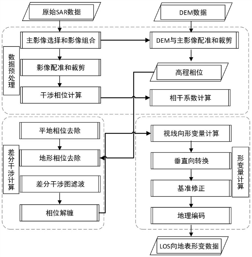
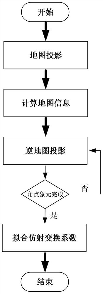
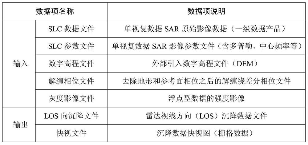
[0079] Such as Figure 1-4 As shown, according to the method for estimating the deformation amount in the LOS direction of the novel differential InSAR described in the embodiment of the present invention, the method includes the following specific steps:

[0080] Step 1, data preprocessing, the data preprocessing includes: SAR main image selection and image combination, image registration and cropping, DEM and SAR main image registration and cropping, interferometric phase calculation, where...


PUM


Abstract

The invention discloses a novel differential InSAR LOS direction deformation quantity estimation method comprising the following steps that: data preprocessing: SAR main image selection and image combination are carried out to generate image pairs on the premise of satisfying space baseline and time baseline requirements, registration is carried out according to DEM and the selected SAR main image, the DEM scope is clipped to be consistent with the SAR main image scope, pre-filtering is carried out on the registered main image and the registered auxiliary image, and calculatinon is conducted to generate an interferogram; differential interference calculation: a flat ground phase is calculated according to space baseline parameters and earth ellipsoid parameters, a terrain phase is calculated by using the registered DEM, a differential interferogram is generated from the interferometric phase, a coherence map is generated by using filtered main and auxiliary image differential interferometric phase pixels, and the phase-wound differential interferogram is unwrapped; lOS direction deformation quantity calculation: unwrapping phases are converted into deformation quantity in the sightline direction according to radar wavelength parameters in combination with external auxiliary data after phase-to-deformation calculation is carried out, and geocoding is carried out through DEM products.

Description

technical field [0001] The invention relates to the field of radar technology for surveying and remote sensing, in particular to a method for estimating the deformation amount in the LOS direction of a novel differential InSAR. Background technique [0002] Most of the existing monitoring methods are to install a variety of sensors on the ground for monitoring, vertical inclination holes, external deformation observation piers, vertical displacement, measuring points, multi-point displacement meters, GNSS, anchor cable dynamometers, anchor cable dynamometers , anchor tendon dynamometer, osmometer, etc. The measurement content is mostly internal deformation monitoring of the cracked body, external deformation monitoring, seepage pressure and support body stress monitoring, etc. The advantages of these methods are high measurement accuracy and reliable results. The disadvantages are that it consumes a lot of manpower and material resources, high cost, sparse measurement points...

Claims


Application Information

Patent Timeline
Patent Type & Authority Applications(China)
IPC IPC(8): G01S13/90
CPCG01S13/9005
Inventor 林艳生肖剑刘思谋白士新张金宝
Owner 中冶(北京)交通科技发展有限公司
Learn More