
Power equipment state monitoring and fault identification method and system

A power equipment and fault identification technology, applied in the field of equipment fault detection, can solve problems such as high risk, high cost, and lack of fault early warning capabilities, and achieve the effects of improving safety, improving identification capabilities, and improving fault early warning capabilities

Active Publication Date: 2020-12-08
CHINA POWER INVESTMENT CORPORATION +3
View PDF3 Cites 5 Cited by
  • Summary
  • Abstract
  • Description
  • Claims
  • Application Information

AI Technical Summary

Problems solved by technology

However, at present, power plants generally select signals such as temperature, pressure, and vibration as the state parameters of each power equipment, which requires sensors to perform one-to-one contact measurement, which is costly and does not have good fault warning capabilities. On the other hand, many equipment Parameters require inspection personnel to hold instruments and measure them close to electrical equipment, which is highly dangerous

Method used


Image

  • Power equipment state monitoring and fault identification method and system
  • Power equipment state monitoring and fault identification method and system
  • Power equipment state monitoring and fault identification method and system

Examples


Embodiment Construction

[0063] The following will clearly and completely describe the technical solutions in the embodiments of the present invention with reference to the accompanying drawings in the embodiments of the present invention. Obviously, the described embodiments are only some of the embodiments of the present invention, not all of them. Based on the embodiments of the present invention, all other embodiments obtained by persons of ordinary skill in the art without making creative efforts belong to the protection scope of the present invention.

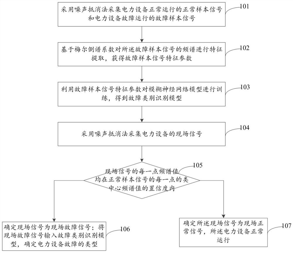
[0064] The object of the present invention is to provide a method and system for state monitoring and fault identification of electric equipment, so as to improve the safety, efficiency and accuracy of electric equipment fault detection, and reduce the cost of electric equipment fault detection.

[0065] In order to make the above objects, features and advantages of the present invention more comprehensible, the present invention will be further d...


PUM


Abstract

The invention provides a power equipment state monitoring and fault identification method and system. According to the method, the sound source signals are collected based on the noise cancellation method, the sensitivity to the environment is reduced, and the sound signal processing precision can be improved. The power equipment is pre-monitored by judging whether the frequency spectrum value ofeach point of the field signal is within the confidence coefficient of the class center frequency spectrum value of each point of the normal sample signal or not, the field signal of the power equipment is screened, and a small number of field fault signals needing fault identification are screened out, so that real-time monitoring is facilitated, and the fault identification efficiency is improved. The algorithm processing speed is improved, the safety, efficiency and accuracy of power equipment fault detection are improved, sensors do not need to be arranged in a one-to-one correspondence mode, and the cost of power equipment fault detection is reduced.

Description

technical field [0001] The invention relates to the technical field of equipment fault detection, in particular to a method and system for state monitoring and fault identification of electric equipment. Background technique [0002] With the continuous development of power plant units, the demand for stable operation of various types of power equipment continues to increase. The application of equipment condition monitoring greatly reduces the possibility of power plant units being shut down due to equipment failures. However, at present, power plants generally select signals such as temperature, pressure and vibration as the state parameters of each power equipment, which require sensors to perform one-to-one contact measurement, which is costly and does not have good fault early warning capabilities. The parameters require the inspection personnel to hold the instrument and measure it close to the power equipment, which is highly dangerous. SUMMARY OF THE INVENTION [...

Claims


Application Information

Patent Timeline
Patent Type & Authority Applications(China)
IPC IPC(8): G06K9/00G06N3/04G06N3/08G01H17/00
CPCG06N3/08G01H17/00G06N3/043G06F2218/04G06F2218/12G06F2218/08
Inventor 华志刚张强王志洁李明宇刘江宁陈以明吴水木杨旭彭雅妮翟永杰
Owner CHINA POWER INVESTMENT CORPORATION
Learn More