
Management and control device for tool and management and control method thereof

A technology for control devices and tools, applied in the direction of collaborative devices, coin-free or similar devices, instruments, etc., can solve problems such as difficulty, low accuracy, lack of use records, etc., to improve the level of safety management , easy to manage and use, strengthen the effect of refinement

Pending Publication Date: 2020-12-08
STATE GRID ZHEJIANG ELECTRIC POWER CO LTD HANGZHOU POWER SUPPLY CO +3
View PDF1 Cites 1 Cited by
  • Summary
  • Abstract
  • Description
  • Claims
  • Application Information

AI Technical Summary

Problems solved by technology

[0002] The scope of use of safety tools is very wide, involving almost every aspect of power production. However, at present, the level of intelligent management of the use and maintenance of safety tools is not high, and the corresponding data collection, analysis, and maintenance are mainly processed manually. Therefore, It is more difficult and less accurate, and there are many problems, such as backward labeling technology, missing usage records, lack of data support for maintenance, inconsistencies between accounts and cards, etc.
[0003] According to the patent search, there are already some safety tool cabinets for storing tools, such as the patent "A Kind of Power Tool Cabinet" (Patent No.: 201510707165.7), but this kind of tool cabinet is mainly for storage and lacks control data. There is an urgent need for a control device for automatic identification, supervision, and storage of tools in electric power production, and the control data and information can be communicated. Therefore, this application develops and designs a control device for tools and its control method

Method used


Image

  • Management and control device for tool and management and control method thereof
  • Management and control device for tool and management and control method thereof

Examples


Embodiment

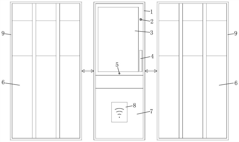
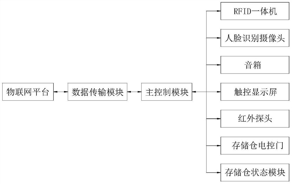
[0018] Example: see figure 1 and figure 2 , the present invention includes a main control cabinet and several storage bins, the main control cabinet is provided with a main control module, a touch display screen, a face recognition camera, a sound box, an infrared probe, an RFID integrated machine, a front inspection door and a storage bin The status module, in which the touch screen is set on the upper front side of the main control cabinet, a face recognition camera and a speaker are installed on one side of the touch screen, an infrared probe is installed under the touch screen, and the front inspection door is set on the main control cabinet. In the lower part of the front side of the cabinet, the RFID all-in-one machine is set in the middle part of the front side of the front inspection door. There are several storage compartments of three specifications, large, medium and small, in the storage compartment. Each storage compartment is equipped with an electric control do...


PUM


Abstract

A management and control device for tools comprises a main control cabinet and a plurality of storage bins, a main control module, a touch display screen, a face recognition camera, a loudspeaker box,an infrared probe, an RFID all-in-one machine, a front access door and a storage bin state module are arranged in the main control cabinet, and a plurality of storage bins of large, medium and smallspecifications are arranged in each storage bin. Each storage bin is provided with a storage bin electric control door, an RFID card is arranged on a tool, the main control module is connected to an Internet of Things platform through a data transmission module, and meanwhile the main control module is further connected with the touch display screen, the face recognition camera, the loudspeaker box, the infrared probe, the RFID all-in-one machine, the storage bin state module and the storage bin electric control doors. The RFID card on the tool is matched with the RFID all-in-one machine. Management and use of tools are separated, full-life-cycle management and control of the tools are easy to achieve, the safety management level is practically improved, waste is avoided to the maximum extent, and management and use of the tools are facilitated.

Description

technical field [0001] The invention belongs to the technical field of management and control of tools, and in particular relates to a management and control device of tools and a control method of the management and control device. Background technique [0002] The scope of use of safety tools is very wide, involving almost every aspect of power production. However, at present, the level of intelligent management of the use and maintenance of safety tools is not high, and the corresponding data collection, analysis, and maintenance are mainly processed manually. Therefore, It is difficult and the accuracy is not high, and there are many problems, such as backward labeling technology, missing usage records, lack of data support for maintenance, and inconsistency between accounts and cards. [0003] According to the patent search, there are already some safety tool cabinets for storing tools, such as the patent "A Kind of Power Tool Cabinet" (Patent No.: 201510707165.7), but ...

Claims


Application Information

Patent Timeline
IPC IPC(8): G07F17/12G07F9/02H04L29/06G06K9/00G06K17/00G07C9/00
CPCG07F17/12G07F9/026G07C9/00563G07C9/00571H04L63/0861G06K17/0029G06V40/16
Inventor 倪展乐全明王辉东汪李忠温建阳华靚沈亮高俊青孙宇东姚智勇董志会金鑫锋温秀峰孙宇舒驾鹏张勐宓天洲陈潇俞晓峰赵峰施金瑞高加骏胡坚包月华李栋陈豪田晟陈修广
Owner STATE GRID ZHEJIANG ELECTRIC POWER CO LTD HANGZHOU POWER SUPPLY CO
Learn More