Method of optimizing spectral efficiency in an mpls interconnection context

Inactive Publication Date: 2019-06-20
THALES SA
View PDF0 Cites 1 Cited by
  • Summary
  • Abstract
  • Description
  • Claims
  • Application Information

AI Technical Summary

Benefits of technology

This patent talks about a way to optimize the use of satellite resources for communication between two devices, such as a gateway and a terminal. The invention is especially useful when data packets have multiple labels for MPLS interconnection with other networks. The technical effect is an efficient use of spectral resources for satellite communication.

Problems solved by technology

One of the main constraints in current satellite communication systems resides in the fact that the radiocommunications resources are very limited, with data streams, notably multimedia streams, exhibiting significant demands in terms of constancy of the bitrate offered but also in terms of lag in forwarding the information across the communication system.
These communications exhibit heavy constraints in respect of integrity and forwarding guarantees.
In all cases, the air interface, and more generally the various resources of the system, are greatly affected by the extra bitrate engendered by the transmission of the switching labels, thereby correspondingly reducing the communication system's performance.
It requires an initial phase of prior handshaking of the hosts for each session of exchanges, and is complex to implement.
Moreover, it generates, in this initial handshaking phase, a significant quantity of data, thus running counter to the initial objective of optimizing the spectral efficiency.
It is thus notably not suitable for communications of small messages (a few bytes or tens of bytes), transmitted for example during TCP connections.
However, this solution can only be implemented at the transmission end, and makes it possible to delete only a single MPLS label.

Method used


Image

  • Method of optimizing spectral efficiency in an mpls interconnection context
  • Method of optimizing spectral efficiency in an mpls interconnection context
  • Method of optimizing spectral efficiency in an mpls interconnection context

Examples


Embodiment Construction

[0049]By “terminal” is meant a communicating device, which may be fixed (for example on the roof of a building) or mobile (for example on a mobile carrier, notably a piloted aircraft or a drone).

[0050]By “gateway” is meant the subset of a ground station which communicates on one side with a satellite, and on the other side with a local network.

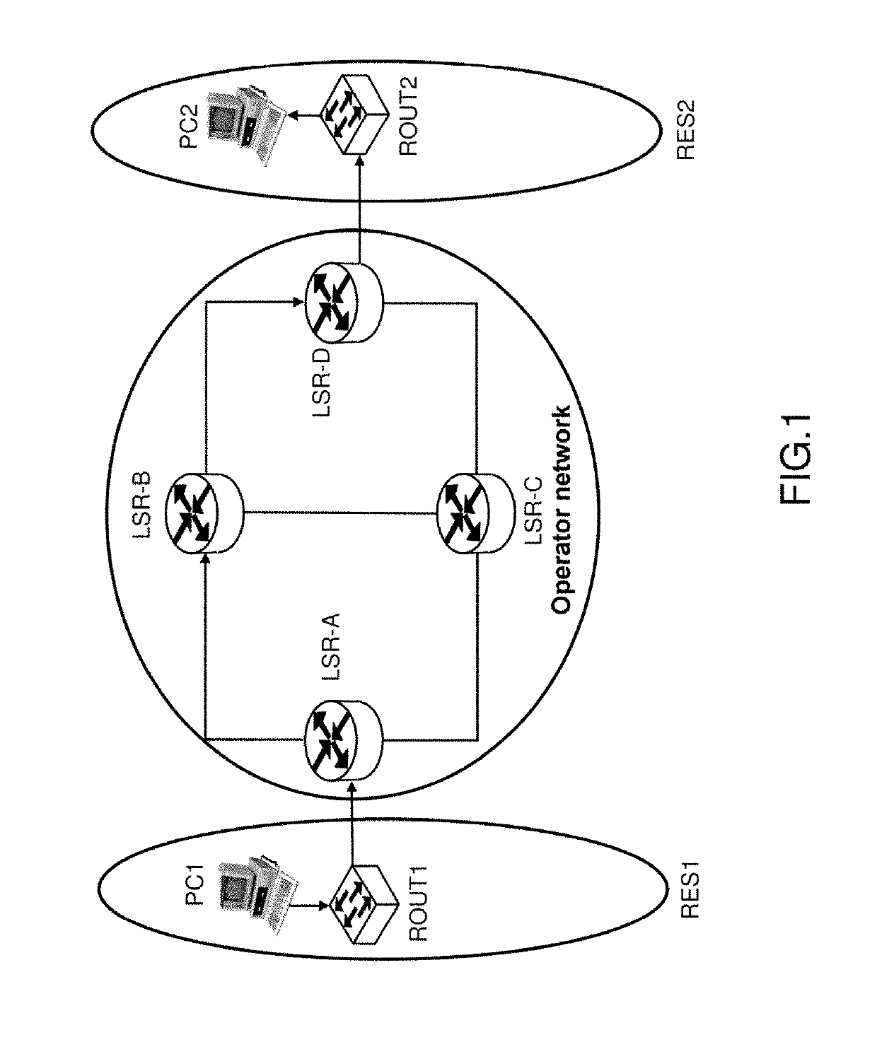
[0051]By “MPLS interconnection context” is meant the possibility of making a communication device, notably a gateway or a terminal, dialogue with MPLS routers.

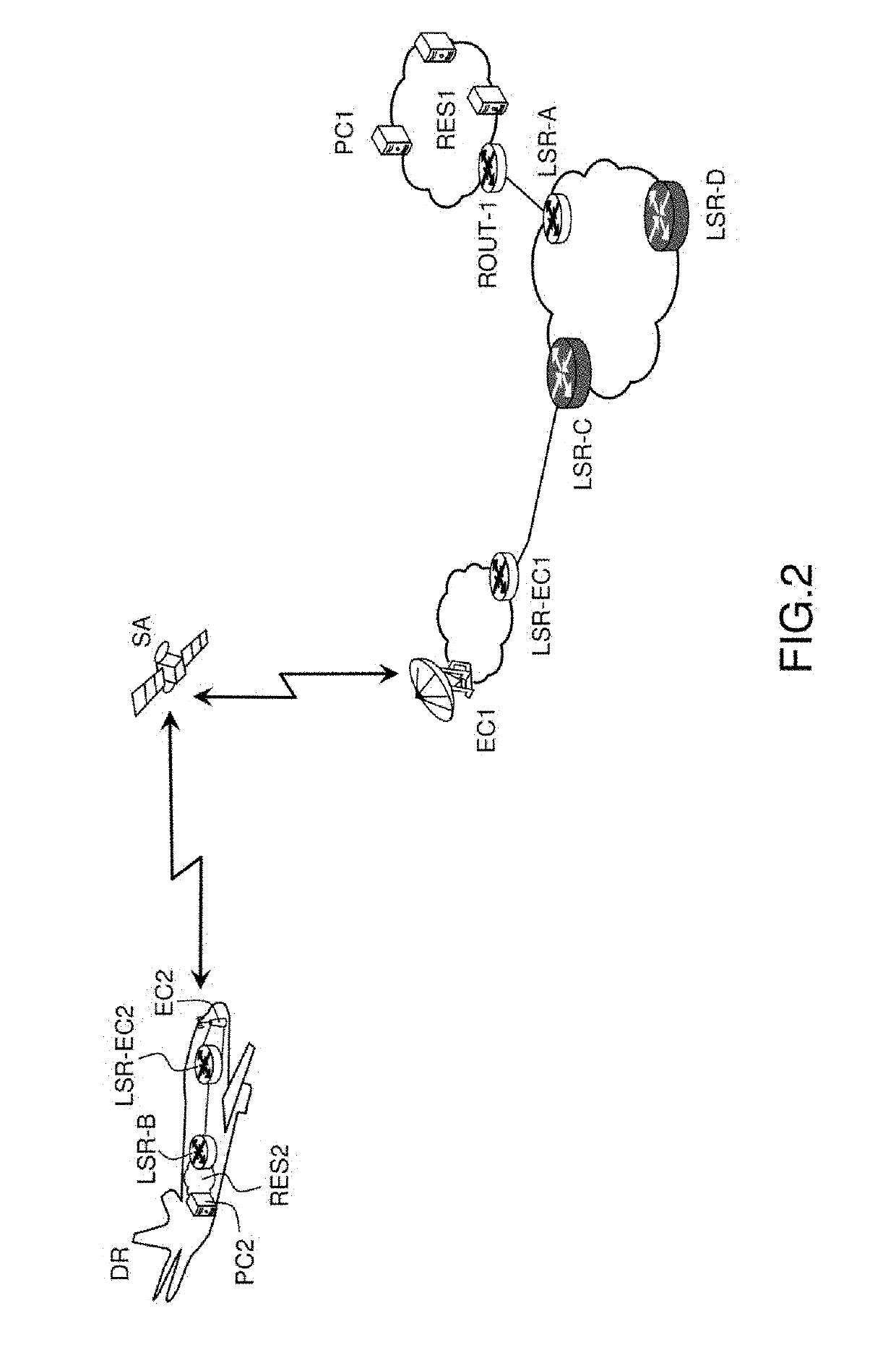
[0052]FIG. 2 schematically illustrates a system for communication on a satellite link interface. The system consists of a user segment, of a ground segment and of a space segment. The user segment comprises notably a communication device EC2 which may be a terminal. The terminal receives the multimedia services to which it has subscribed, and can transmit data via a return voice which may be terrestrial or by satellite. The terminal moreover comprises a means of interconnection with a ne...


PUM


Abstract

A method is provided for transmitting data between a first communication device and a second communication device, the first communication device being configured to receive from a router connected to the first communication device data in the form of packets comprising at least one intermediate level label, wherein the method comprises at least: a) an initial step of connection setup, comprising at least: a1) a sub-step of transmitting the intermediate level label; a2) a sub-step of recording the intermediate level label; b) a step of transmitting the data packet, comprising: b1) a sub-step of deleting the intermediate level label transmitted by the router connected to the first communication device in the data packet; b2) A sub-step of transmitting the de-encapsulated data packet, with a view to being reconstructed after its transmission.

Description

CROSS-REFERENCE TO RELATED APPLICATIONS[0001]This application claims priority to foreign French patent application No. FR 1701325, filed on Dec. 19, 2017, the disclosure of which is incorporated by reference in its entirety.FIELD OF THE INVENTION[0002]The invention lies in the field of systems for satellite communication between two communication devices, notably between a gateway and a terminal. The terminal may be embedded on board a vehicle, notably an aircraft, in particular a drone. The invention is situated in a context of optimization of the use of the bandwidth on the radio linkup between two communication devices, in a context of MPLS interconnection with other networks.BACKGROUND[0003]One of the main constraints in current satellite communication systems resides in the fact that the radiocommunications resources are very limited, with data streams, notably multimedia streams, exhibiting significant demands in terms of constancy of the bitrate offered but also in terms of l...

Claims


Application Information

Patent Timeline
IPC IPC(8): H04L12/723H04L12/46H04B7/185H04L45/50
CPCH04L45/50H04L69/22H04B7/18513H04L12/4633H04L69/04H04B7/18508
Inventor VAN WAMBEKE, NICOLASROGNANT, PIERRE
Owner THALES SA
Why Eureka
Try Eureka