
High-speed automatic chip mounter capable of avoiding chip mounting deviation

An automatic placement machine and placement technology, applied in the direction of cleaning methods, electrical components, cleaning methods and appliances using gas flow, can solve problems such as patch offset and insufficient adsorption force, and avoid patch offset , avoid insufficient adsorption force, and ensure the effect of precision

Pending Publication Date: 2020-12-08
孙传保
View PDF8 Cites 7 Cited by
  • Summary
  • Abstract
  • Description
  • Claims
  • Application Information

AI Technical Summary

Problems solved by technology

[0004] The purpose of the present invention is to provide a high-speed automatic placement machine that avoids placement deviation, so as to solve the above-mentioned background technology. The current high-speed automatic placement machine on the market pursues fast and accurate in use, but often suffers from Due to the low air pressure of the placement nozzle, the adsorption force is insufficient, and the placement deviation occurs.

Method used


Image

  • High-speed automatic chip mounter capable of avoiding chip mounting deviation
  • High-speed automatic chip mounter capable of avoiding chip mounting deviation
  • High-speed automatic chip mounter capable of avoiding chip mounting deviation

Examples


Embodiment Construction

[0025] The following will clearly and completely describe the technical solutions in the embodiments of the present invention with reference to the accompanying drawings in the embodiments of the present invention. Obviously, the described embodiments are only some, not all, embodiments of the present invention. Based on the embodiments of the present invention, all other embodiments obtained by persons of ordinary skill in the art without making creative efforts belong to the protection scope of the present invention.

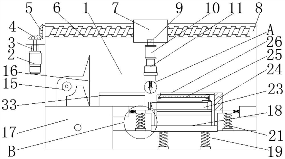
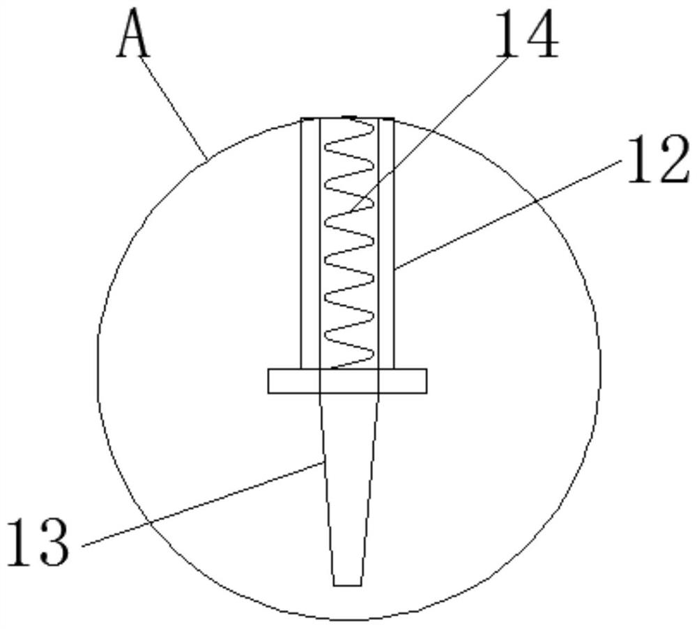
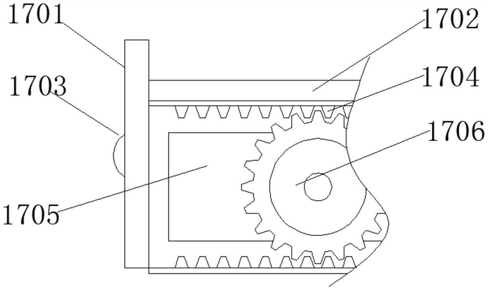
[0026] see Figure 1-6, the present invention provides a technical solution: a high-speed automatic chip mounter that avoids chip offset, including a device main body 1, a first motor 2, a rotating shaft 3, a first gear 4, a second gear 5, a first screw rod 6. Connection sleeve 7, first bearing 8, rotary joint sleeve 9, second motor 10, suction nozzle connecting rod 11, telescopic rod 12, mounting suction nozzle 13, first spring 14, dust collector 15, air outl...


PUM


Abstract

The invention discloses a high-speed automatic chip mounter capable of avoiding chip mounting deviation, and the chip mounter comprises an equipment main body, a first gear, a connecting sleeve, a first bearing, a suction nozzle connecting rod, a mounting suction nozzle, a dust collection box, a workbench, a third spring, a clamping device, a PCB, an anti-deviation limiting groove, and a sliding rail. A first motor is arranged at the side end of the equipment main body. According to the high-speed automatic chip mounter capable of avoiding chip mounting deviation, the anti-deviation limiting groove and the second sliding block are arranged, the anti-deviation limiting groove and the movable adjusting block of the same specification are selected according to the type of the chip mounting, so that the second sliding block fixedly connected with the adjusting block moves, and a sliding structure is formed between the second sliding block and the sliding rail; and the anti-deviation limiting groove can be driven to move horizontally, the shape of the limiting groove is consistent with the shape of a surface-mounted element, so that the element to be surface-mounted is pre-aligned, andthe problems of insufficient adsorption force and surface-mounted deviation caused by over-low air pressure of the surface-mounted suction nozzle are avoided.

Description

technical field [0001] The invention relates to the technical field of placement, in particular to a high-speed automatic placement machine that avoids deviation of placement. Background technique [0002] The placement machine is a kind of equipment that places and mounts electronic components on the PCB. It is divided into two types: manual and fully automatic. [0003] High-speed automatic placement machines are common equipment on SMT production lines. High-speed automatic placement machines are needed in the processing workshops of some factories. There are many types of high-speed automatic placement machines on the market, but the current ones on the market This type of high-speed automatic placement machine pursues speed and precision when using it, but often the suction force is insufficient due to the low air pressure of the placement nozzle, and placement deviation occurs. Therefore, there is an urgent need for improvement in the market to avoid placement deviatio...

Claims


Application Information

Patent Timeline
Patent Type & Authority Applications(China)
IPC IPC(8): H05K13/04H05K13/00B08B5/04
CPCB08B5/04H05K13/0061H05K13/0409
Inventor 孙传保
Owner 孙传保
Learn More