Automatic rare earth ore feeding mixer

A technology of automatic feeding and mixing machine, which is applied to mixers, mixers with rotary mixing devices, mixer accessories, etc., can solve the problems of automatic feeding and other problems, and achieve the effect of convenient use

Inactive Publication Date: 2020-12-11
袁启进
View PDF14 Cites 6 Cited by
  • Summary
  • Abstract
  • Description
  • Claims
  • Application Information

AI Technical Summary

Problems solved by technology

[0005] In order to overcome the shortcomings of the current rare earth mixing method that cannot be automatically fed, the technical problem of the present invention is to provide a rare earth ore automatic feeding and mixing machine that can automatically feed and improve the rare earth mixing efficiency

Method used


Image

  • Automatic rare earth ore feeding mixer
  • Automatic rare earth ore feeding mixer
  • Automatic rare earth ore feeding mixer

Examples


Embodiment 1

[0020] A rare earth ore automatic feeding mixer, such as Figure 1-4 As shown, it includes a sedimentation tank 1, a stirring assembly 2, a mixing tank 3, a material control assembly, a storage hopper 4 and an adjustment assembly 5. The rear side of the sedimentation tank 1 is equipped with a stirring assembly 2 for stirring and mixing by rotation. The sedimentation tank 1 The middle part of the rear side is fixed with a mixing tank 3 by bolts, and a material control component is installed in the mixing tank 3, and four storage hoppers 4 are fixed on the top of the rear side of the sedimentation tank 1 through bolts. Adjustment assembly 5 for adjustment by means of rotation.

[0021] When it is necessary to use the device to mix rare earth metals, the rare earth metals to be mixed are first placed in the storage hopper 4, and then the stirring assembly 2 is controlled to start working, and the stirring assembly 2 triggers the material control assembly to start working, so that...

Embodiment 2

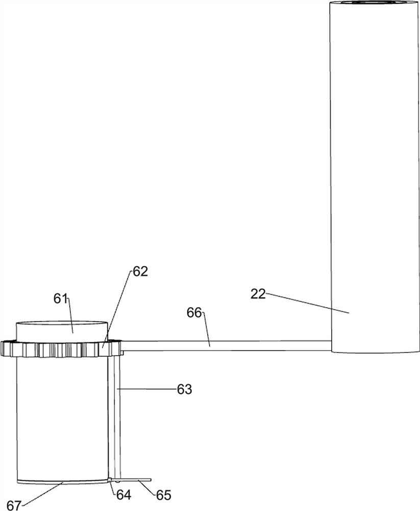
[0029] On the basis of Example 1, such as figure 1 and 5 As shown, a discharge assembly 6 is also included, and the front side of the bottom of the mixing bucket 3 is equipped with a discharge assembly 6 that is discharged by rotating. The discharge assembly 6 includes a discharge pipe 61, a ring gear 62, a connecting rod 63, Rotating plate 64, swing rod 65, telescopic push rod 66 and discharge plate 67, the front side of the bottom of the mixing bucket 3 is provided with a discharge pipe 61, the upper part of the discharge pipe 61 is keyed with a gear ring 62, and the rear side of the bottom of the gear ring 62 is welded There is a connecting rod 63, the bottom of the discharge pipe 61 is rotated by a torsion spring 38 and is provided with a rotating plate 64, the front side of the rotating plate 64 is welded with a discharge plate 67, and the rear side of the rotating plate 64 is welded with a swing bar 65, and the connecting rod 63 is connected to the swinging plate 64. Ro...


PUM


Abstract

The invention relates to a rare earth ore mixer, in particular to an automatic rare earth ore feeding mixer. The invention provides an automatic rare earth ore feeding mixer which can automatically feed rare earth ore and improve the rare earth mixing efficiency. The automatic rare earth ore feeding mixer comprises a sedimentation tank; a stirring assembly mounted on the sedimentation tank and used for stirring and mixing in a rotating manner; a stirring barrel mounted on the sedimentation tank; a material control assembly mounted in the stirring barrel; a storage hopper mounted on the sedimentation tank; and an adjusting assembly mounted between the material control assembly and the stirring barrel and carrying out adjustment in a rotating manner. According to the invention, through cooperation of the stirring assembly, the material control assembly and the adjusting assembly, rare earth can be automatically put down and mixed, discharging of the rare earth can be controlled accordingto needs, the requirement for rare earth mixing is better met, the mixed rare earth can be automatically discharged through a discharging assembly, and the equipment is more convenient to use.

Description

technical field [0001] The invention relates to a rare earth ore mixing machine, in particular to an automatic feeding and mixing machine for rare earth ore. Background technique [0002] Rare earth is a collective term for 17 chemical elements including scandium, yttrium and lanthanides in group III of the periodic table. It generally exists in the form of oxides and is a non-renewable resource. Rare earths are actually not rare, but the process of turning them into useful materials is complex, cumbersome and expensive, hence the name "rare earths". These 17 elements can usually be divided into light rare earths and heavy rare earths, among which heavy rare earths are more valuable. In the process of rare earth production, it is often necessary to mix multiple rare earths. [0003] The patent authorization announcement number is CN206519107U, which discloses a rare earth mixture stirring device, which includes a housing, a feeding cylinder and a decelerating motor. The d...

Claims


Application Information

Patent Timeline
Patent Type & Authority Applications(China)
IPC IPC(8): B01F7/18B01F15/02
CPCB01F27/191B01F27/90B01F35/71
Inventor 袁启进
Owner 袁启进
Why Eureka
Try Eureka