Core roller multi-station device for ring rolling machine

A multi-station, ring rolling machine technology, applied in metal rolling and other directions, can solve the problems of bending deformation damage and low service life of the core roll, and achieve the effects of improving firmness, improving practicability and facilitating adjustment.

Inactive Publication Date: 2020-12-11
ZHUCHENG SHENGYANG MACHINERY
View PDF6 Cites 0 Cited by
  • Summary
  • Abstract
  • Description
  • Claims
  • Application Information

AI Technical Summary

Problems solved by technology

[0002] As we all know, the main function of the core roller on the ring rolling machine is to position and squeeze the ring workpiece, so as to adjust the wall thickness of the ring workpiece. The position is located on the lower side of the core roll, the distance between the contact position and the fulcrum on the upper side of the core roll is relatively large, and the idle length on the upper side of the core roll is relatively large. When the workpiece squeezes the core roll, it is easy to cause bending deformation and damage to the core roll. resulting in a lower service life

Method used


Image

  • Core roller multi-station device for ring rolling machine
  • Core roller multi-station device for ring rolling machine
  • Core roller multi-station device for ring rolling machine

Examples


Embodiment Construction

[0021]The specific implementation manners of the present invention will be further described in detail below in conjunction with the accompanying drawings and embodiments. The following examples are used to illustrate the present invention, but are not intended to limit the scope of the present invention.

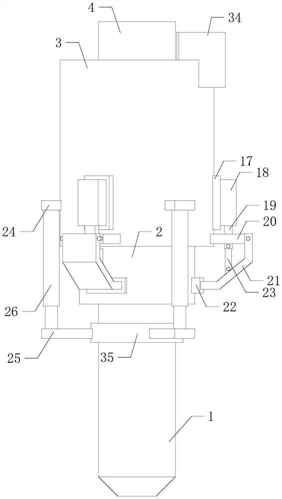
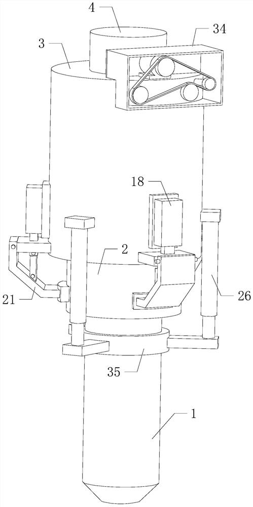
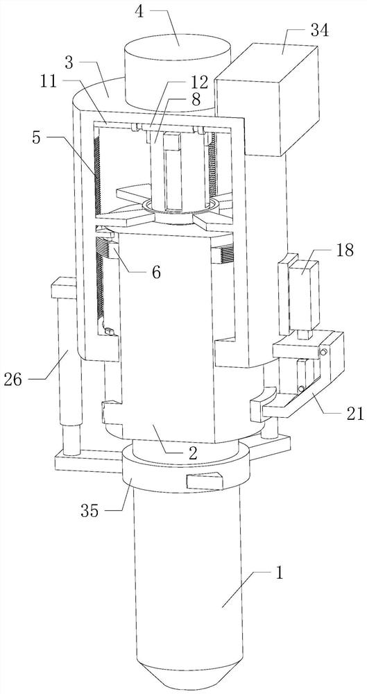
[0022] Such as Figure 1 to Figure 7 As shown, a core roller multi-station device for a ring rolling machine of the present invention, when it is working, turns on the motor 13, and the motor 13 drives two sets of rotating shafts 11 to rotate through four sets of pulleys 15 and synchronous belts 16, and the supporting shaft 14 The belt pulley 15 mainly carries out circular processing on the synchronous belt 16, and at the same time, the upper side of the outer wall of the pulley 15 on the rear shaft 11 is in contact with the outer wall of the synchronous belt 16, so that the rotation directions of the two groups of shafts 11 are opposite, and the two groups of shafts 11 pas...


PUM


Abstract

The invention relates to the technical field of ring rolling equipment, and particularly relates to a core roller multi-station device for a ring rolling machine. The height position of a core rollercan be conveniently adjusted by adjusting the station of the core roller, so that when a workpiece with a small height is machined, the workpiece is in contact with the upper side of the core roller,the situation that the distance between the contact position of the workpiece and the core roller and the top fulcrum of the core roller is large, and consequently the workpiece causes overstock deformation is avoided, the idle length of the upper side of the core roller is reduced, the core roller is conveniently protected, the service life of the equipment is prolonged, and the practicability and reliability are improved. The core roller multi-station device comprises the core roller, an adjusting shaft, an adjusting bin and a connecting shaft, wherein the bottom of the adjusting shaft is mounted at the top of the core roller; a cavity is formed in the adjusting bin; a through opening is formed in the bottom of the cavity in a communicating mode; the top of the adjusting shaft is inserted into the cavity through the through opening; and the outer wall of the adjusting shaft is in contact with the inner wall of the through opening and can slide relative to the inner wall of the through opening.

Description

technical field [0001] The invention relates to the technical field of ring rolling equipment, in particular to a core roller multi-station device for a ring rolling machine. Background technique [0002] As we all know, the main function of the core roller on the ring rolling machine is to position and squeeze the ring workpiece, so as to adjust the wall thickness of the ring workpiece. The position is located on the lower side of the core roll, the distance between the contact position and the fulcrum on the upper side of the core roll is relatively large, and the idle length on the upper side of the core roll is relatively large. When the workpiece squeezes the core roll, it is easy to cause bending deformation and damage to the core roll. resulting in a lower service life. Contents of the invention [0003] In order to solve the above-mentioned technical problems, the present invention provides a method for adjusting the position of the core roller, which can convenie...

Claims


Application Information

Patent Timeline
Patent Type & Authority Applications(China)
IPC IPC(8): B21H1/06
CPCB21H1/06
Inventor 魏本伟王恩武侯文杰李国锋郭凯
Owner ZHUCHENG SHENGYANG MACHINERY
Why Eureka
Try Eureka