
Clamping and fixing device for processing treatment of complex-form materials

A material processing, clamping and fixing technology, applied in the field of machining, can solve problems such as poor stability, low machining accuracy, and unfavorable use, and achieve the effects of improving stability, improving machining accuracy, and facilitating positioning and machining work.

Inactive Publication Date: 2020-12-11
赵静
View PDF13 Cites 1 Cited by
  • Summary
  • Abstract
  • Description
  • Claims
  • Application Information

AI Technical Summary

Problems solved by technology

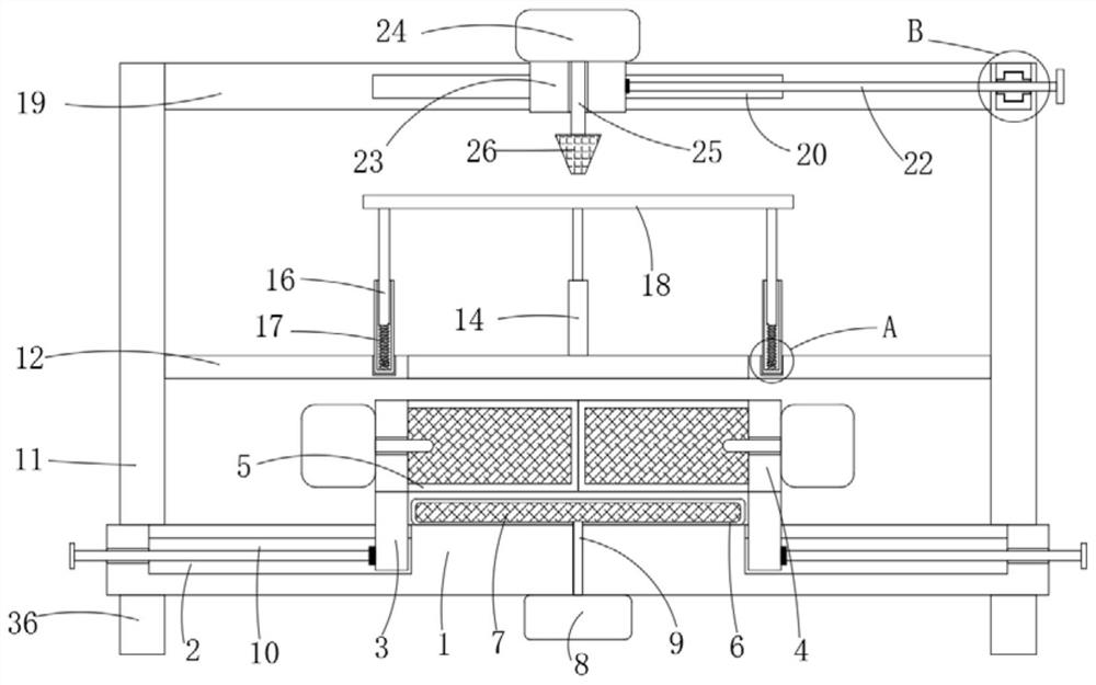
[0004] The purpose of the present invention is to solve the shortcomings in the prior art, such as: the existing clamping and fixing device has poor stability and low processing accuracy when processing materials with complex shapes, which is greatly unfavorable for users to use

Method used


Image

  • Clamping and fixing device for processing treatment of complex-form materials
  • Clamping and fixing device for processing treatment of complex-form materials
  • Clamping and fixing device for processing treatment of complex-form materials

Examples


Embodiment 1

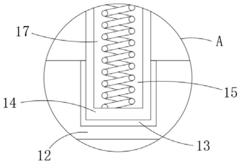
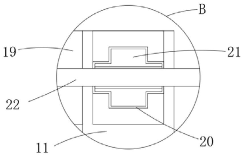
[0023] refer to Figure 1-4 , a clamping and fixing device for complex shape material processing, including a base 1, four feet 36 arranged symmetrically to each other are fixedly connected to the lower end surface of the base 1, and the feet 36 can complete the supporting work for the base 1 more stably , and then complete the supporting work of the whole device, and the feet 36 can keep the base 1 away from the supporting surface, so that the power supply equipment 8 under the base 1 can safely complete the power supply work, and the upper end surface of the base 1 is provided with two Symmetrically arranged sliding grooves 2, sliding blocks 3 are slidably connected in the two sliding grooves 2, and clamping plates 4 are fixedly connected on the side walls of the two sliding blocks 3 away from the sliding groove 2, and the two clamping plates 4 The side walls close to each other are fixedly connected with elastic bags 5, and the upper end surface of the base 1 is fixedly con...

Embodiment 2

[0028] refer to Figure 5-6 The difference between this embodiment and Embodiment 1 lies in the setting of the two positioning devices. The support ring 12 is provided with two positioning devices arranged in a staggered manner. The staggered arrangement allows the two positioning devices to cooperate to complete the center positioning of the material, which is extremely It greatly facilitates the user to accurately process regular and symmetrical materials. The two positioning devices all include two round rods 27 that are slidably connected in the annular groove 13. The heights of the round rods 27 in the two positioning devices are different, so that Effectively avoid the two positioning devices from interfering with each other during work. The sliding connection of the round rod 27 in the annular groove 13 facilitates the user to move the round rod 27, and then the positioning device can complete the positioning work at a suitable position, which is also convenient for the ...


PUM


Abstract

The invention discloses a clamping and fixing device for processing treatment of complex-form materials. The clamping and fixing device comprises a base, wherein two sliding grooves which are symmetrically arranged are formed in the upper end surface of the base; sliding blocks are connected in the two sliding grooves in a sliding mode; clamping plates are fixedly connected to the side walls, faraway from the sliding grooves, of the two sliding blocks; elastic bags are fixedly connected to the side walls, close to each other, of the two clamping plates; a supporting bag is fixedly connected to the upper end surface of the base; electrorheological fluid is arranged in the elastic bags and the supporting bag; power supply equipment is arranged on the side walls, far away from each other, ofthe two clamping plates and the lower end surface of the base; and power supply rods are arranged on the three pieces of power supply equipment. According to the clamping and fixing device, the stability of clamping and fixing work during the processing of the complex-form materials is improved, the accuracy of material processing is improved, and the use of a user is greatly facilitated.

Description

technical field [0001] The invention relates to the technical field of machining, in particular to a clamping and fixing device for processing materials with complex shapes. Background technique [0002] Machining is a process of changing the shape or performance of a workpiece through a mechanical device. In the process of machining, in order to ensure that the corresponding processing equipment can successfully complete the processing of the corresponding material, it is necessary to fix the material to be processed. Appropriate clamping fixtures are required for this purpose. [0003] The existing clamping and fixing device uses two clamping plates to complete the extrusion and fixing of the material to be processed, but because the clamped surface of a large number of materials to be processed cannot be kept flat, the existing clamping and fixing device When clamping and fixing, there will be instability such as shaking, which will greatly reduce the stability of the pr...

Claims


Application Information

Patent Timeline
IPC IPC(8): B23Q3/08
CPCB23Q3/086
Inventor 赵静
Owner 赵静
Learn More