
Polishing layer for polishing brush, polishing brush, polishing machine, and related preparation method

A polishing brush and polishing layer technology, which is applied in the field of polishing layer, can solve the problems of affecting the grinding and polishing effect, uneven grinding and polishing of the glass side, and the glass side is not effectively polished and polished, so as to improve the grinding and polishing effect , Grinding and polishing evenly, enhancing the effect of fixing

Pending Publication Date: 2020-12-11
嘉贺光电科技(惠州)有限公司
View PDF0 Cites 0 Cited by
  • Summary
  • Abstract
  • Description
  • Claims
  • Application Information

AI Technical Summary

Problems solved by technology

[0002] In the prior art, the polishing layer of the cylindrical polishing brush is generally composed of annular polishing teeth, and an axial gap is easily formed between two adjacent rows of polishing teeth of the cylindrical polishing brush. During polishing, since the cylindrical polishing brush is constantly rotating, when it rotates to the gap between two adjacent rows of polishing teeth, the side of the glass in contact with the polishing brush will not be effectively polished and polished, resulting in glass side Uneven side grinding and polishing affect the grinding and polishing effect

Method used


Image

  • Polishing layer for polishing brush, polishing brush, polishing machine, and related preparation method
  • Polishing layer for polishing brush, polishing brush, polishing machine, and related preparation method
  • Polishing layer for polishing brush, polishing brush, polishing machine, and related preparation method

Examples


Embodiment Construction

[0046] Exemplary embodiments of the present disclosure will be described in more detail below with reference to the accompanying drawings. Although exemplary embodiments of the present disclosure are shown in the drawings, it should be understood that the present disclosure may be embodied in various forms and should not be limited by the embodiments set forth herein. Rather, these embodiments are provided for more thorough understanding of the present disclosure and to fully convey the scope of the present disclosure to those skilled in the art.

[0047] In the description of the present invention, it should be noted that the terms "center", "upper", "lower", "left", "right", "vertical", "horizontal", "inner", "outer" etc. The indicated orientation or positional relationship is based on the orientation or positional relationship shown in the drawings, and is only for the convenience of describing the present invention and simplifying the description, rather than indicating or...


PUM


Abstract

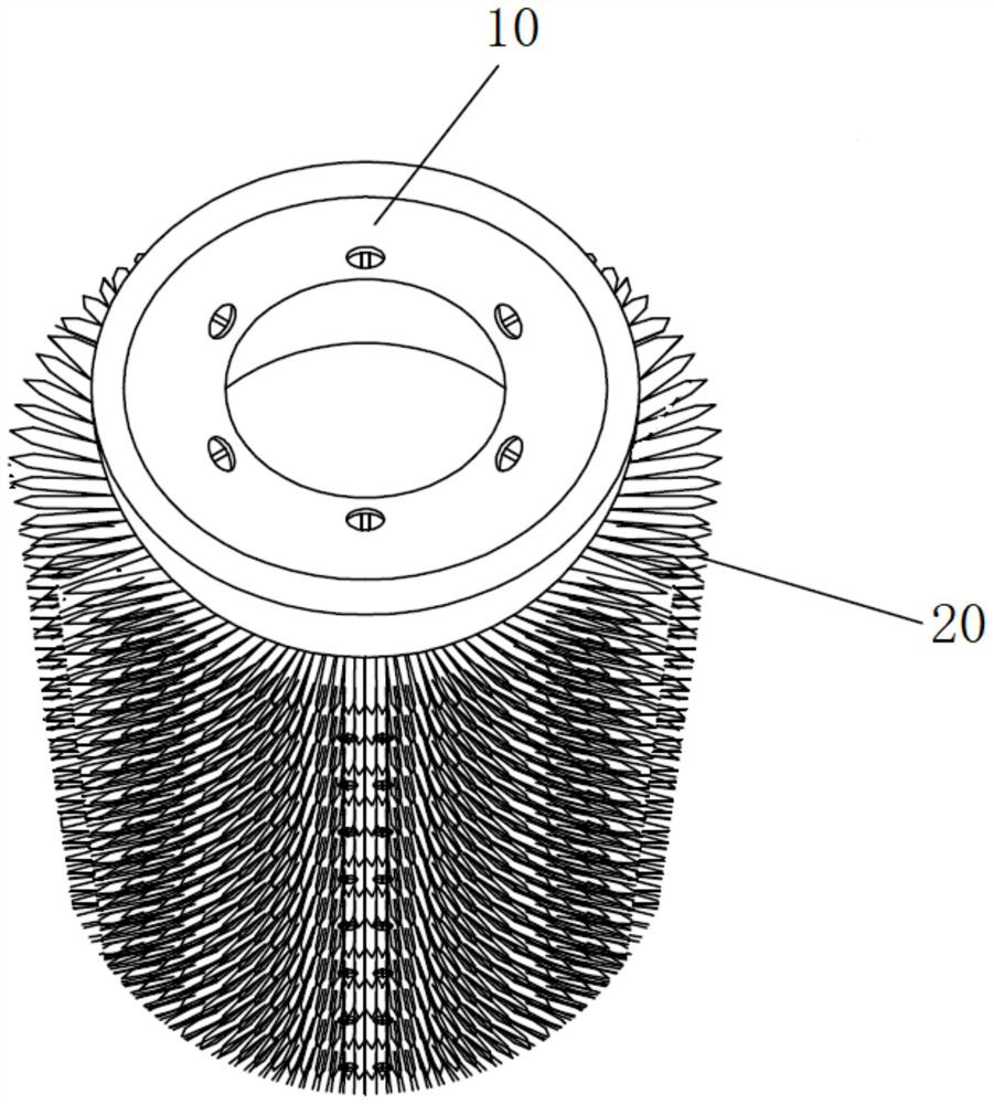
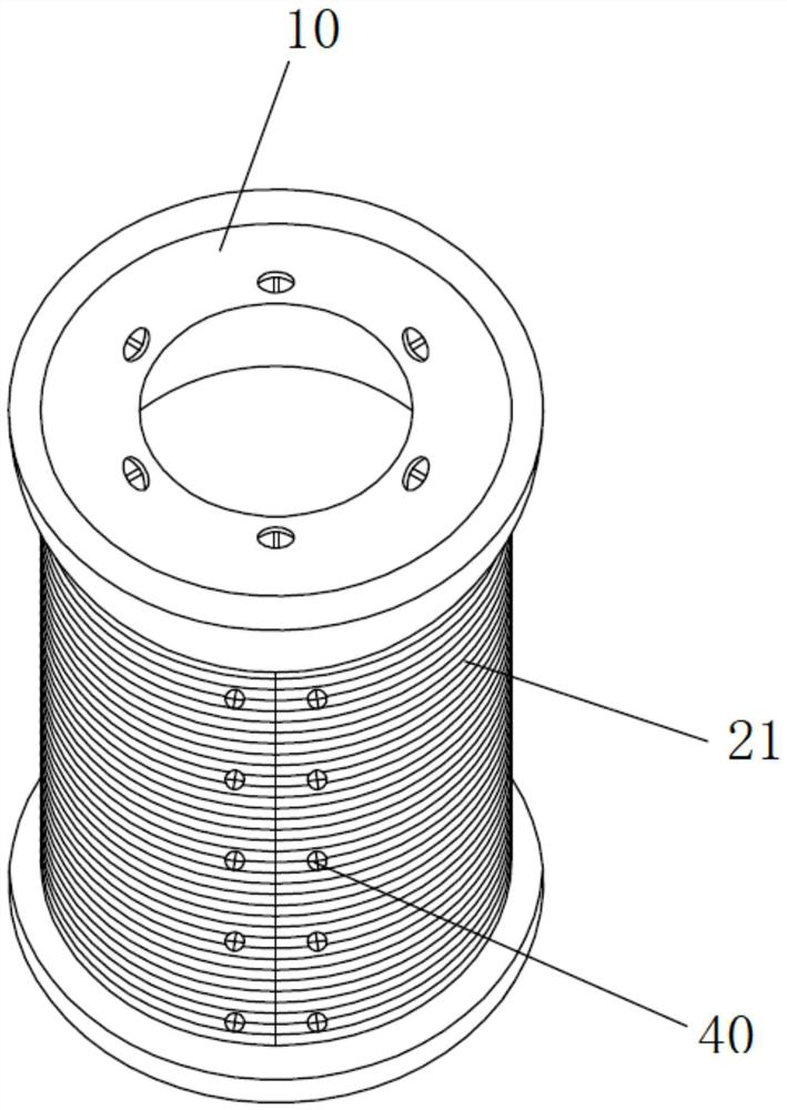
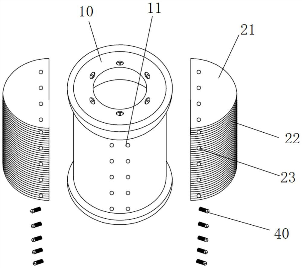
The invention discloses a polishing layer for a polishing brush, the polishing brush, a polishing machine, and a related preparation method. The polishing layer for the polishing brush comprises a fixing layer and at least one polishing rack; a plurality of fixing grooves are formed in the outer surface of the fixing layer and used for fixing the polishing racks; the fixing layer is in the shape of all or part of a cylindrical cambered surface, and the multiple fixing grooves are expansion lines of a spiral curve extending along the outer surface of the fixing layer; each of the polishing racks comprises a plurality of polishing teeth; a plurality of through holes are formed in the ends, away from the polishing teeth, of the polishing racks at intervals; and at least one polishing rack isfixed inside the fixing grooves of the fixing layer. After the polishing racks are fixed in the fixing grooves, the spiral or partially spiral polishing layer is formed, so that an axial gap is not prone to being formed between every two adjacent polishing teeth, and the side edge of a workpiece can be effectively ground and polished. The multiple through holes are formed in the polishing racks atintervals, and when gel is used for fixing, the gel penetrates through the through holes of the polishing racks to fix more firmly.

Description

technical field [0001] The invention relates to a polishing layer for a polishing brush, a polishing brush, a polishing machine and related preparation methods. Background technique [0002] In the prior art, the polishing layer of the cylindrical polishing brush is generally composed of annular polishing teeth, and an axial gap is easily formed between two adjacent rows of polishing teeth of the cylindrical polishing brush. During polishing, since the cylindrical polishing brush is constantly rotating, when it rotates to the gap between two adjacent rows of polishing teeth, the side of the glass in contact with the polishing brush will not be effectively polished and polished, resulting in glass side Uneven side grinding and polishing affect the grinding and polishing effect. Contents of the invention [0003] In view of the above problems, the present invention is proposed to provide a polishing layer for a polishing brush, a polishing brush, a polishing machine and rel...

Claims


Application Information

Patent Timeline
Patent Type & Authority Applications(China)
IPC IPC(8): B24B29/00B24B29/02B24D18/00
CPCB24B29/005B24B29/02B24D18/009
Inventor 蔡林娟
Owner 嘉贺光电科技(惠州)有限公司
Learn More