Automatic bamboo body peeling device
An automatic, bamboo-body technology, applied in mechanical equipment, sugarcane machining, etc., can solve problems such as low work efficiency, inability to control the force of manual smoothing, and excessive elimination of bamboo skins, etc., to achieve high work efficiency and avoid workbenches. more confusing effect
- Summary
- Abstract
- Description
- Claims
- Application Information
AI Technical Summary
Problems solved by technology
Method used
Image
Examples
Embodiment 1
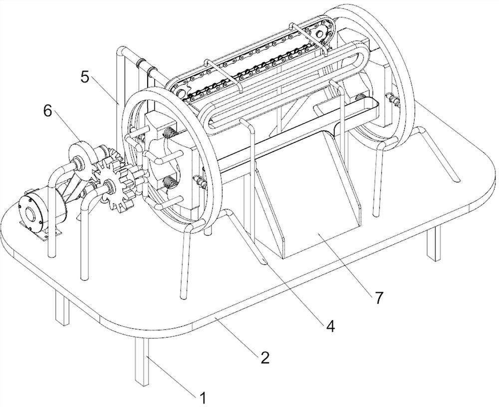
[0047] A kind of bamboo body automatic peeling device, such as Figure 1-2 As shown, it includes a support bracket 1, a workbench 2, a supporting plate 3, a fixing mechanism 4 and a peeling mechanism 5. The support bracket 1 is provided around the bottom of the workbench 2, and the left and right sides of the top of the workbench 2 are provided with supporting plates. 3. Fixing mechanisms 4 are installed on the left and right sides of the top of the workbench 2, and the fixing mechanisms 4 on the left and right sides are all located outside the supporting plates 3 on both sides, and a peeling mechanism 5 is installed on the top of the workbench 2.
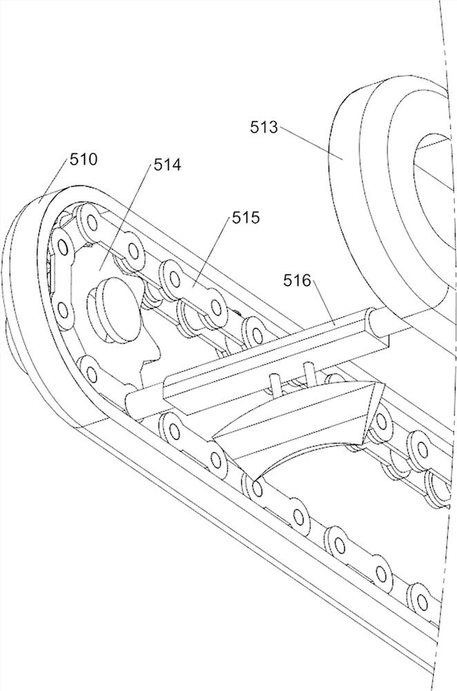
[0048] When the bamboo body needs to be peeled, the staff first puts the bamboo that needs to be peeled into the fixing mechanism 4 and fixes it. Start the parts in the peeling mechanism 5, and the peeling mechanism 5 rotates to peel one side of the bamboo body, and the bamboo skin falls on the workbench 2 under the action of gravi...
Embodiment 2
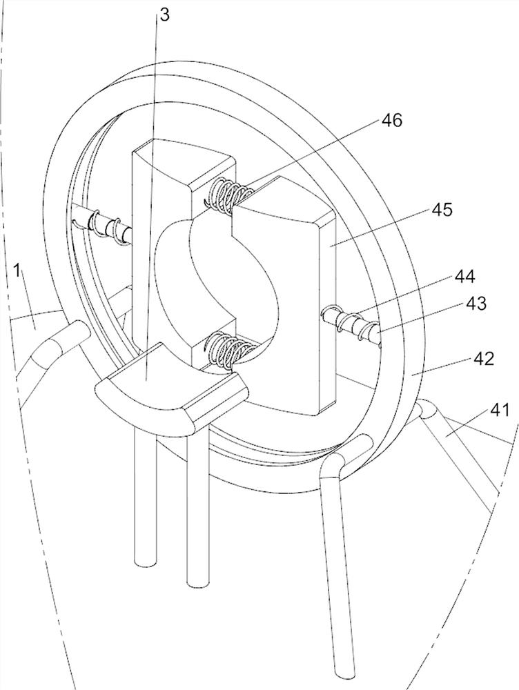
[0050] On the basis of Example 1, such as figure 2 As shown, the fixing mechanism 4 includes a support column 41, a first slide rail 42, a telescopic column 43, a first spring 44, a first fixed plate 45 and a second spring 46, and the top of the workbench 2 is provided with a support column 41 in the front, rear, left, and right sides. , and the support columns 41 on the left and right sides are all located on the outsides of the supporting plates 3 on the left and right sides, the first slide rail 42 is connected between the front and rear support columns 41, and the first slide rail 42 inner walls are slidingly provided with telescopic columns 43 on both sides , the inner side of the telescopic column 43 is provided with a first fixed plate 45, and a second spring 46 is connected between the first fixed plate 45 on both sides, and a spring 46 is connected between the first fixed plate 45 and the inner wall of the first slide rail 42. The first spring 44 .
[0051]When the ...
Embodiment 3
[0055] On the basis of Example 2, such as Figure 5 As shown, a rotating mechanism 6 is also included, and a rotating mechanism 6 is connected between the left side of the top of the workbench 2 and the right side of the first fixed plate 45. The rotating mechanism 6 includes a fourth transmission assembly 61, a double-toothed gear 62, a full gear 63. The third rotating column 64 and the second connecting rod 65. The third rotating column 64 is arranged on the front and rear of the top left side of the workbench 2, and the front and rear third rotating columns 64 are located on the front side of the motor 51, and the third rotating column 64 on the front side The upper part of the column 64 is rotatably connected with a full gear 63, and the upper part of the third rotatable column 64 on the rear side is rotatably connected with a double-toothed gear 62, and the double-toothed gear 62 and the full gear 63 can mesh with each other. The front end of the first rotating shaft 52 i...
PUM
 Abstract
Description
Claims
Application Information
 - R&D
- Intellectual Property
- Life Sciences
- Materials
- Tech Scout
- Unparalleled Data Quality
- Higher Quality Content
- 60% Fewer Hallucinations
Browse by: Latest US Patents, China's latest patents, Technical Efficacy Thesaurus, Application Domain, Technology Topic, Popular Technical Reports.
© 2025 PatSnap. All rights reserved.Legal|Privacy policy|Modern Slavery Act Transparency Statement|Sitemap|About US| Contact US: help@patsnap.com


