Thermal printing method and device and terminal equipment
A technology of thermal printing and thermal printing head, which is applied in the printing field, can solve the problems of uneven printing and blooming, and achieve the effects of uniform density, avoiding blooming and uniform temperature
- Summary
- Abstract
- Description
- Claims
- Application Information
AI Technical Summary
Problems solved by technology
Method used
Image
Examples
Embodiment 1
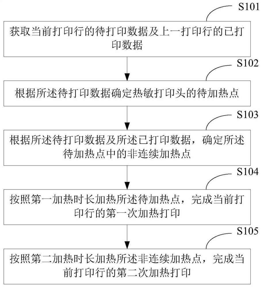
[0038] figure 1 A schematic flowchart of the first thermal printing method provided by the embodiment of the present application is shown, and the details are as follows:
[0039] In S101, the to-be-printed data of the current printing line and the printed data of the previous printing line are acquired.
[0040] In a thermal printer, there is a print data buffer unit. For example, a ring buffer of a thermal printer is a continuous readable memory applied by a Microcontroller Unit (MCU) of the thermal printer for storing print data. Before starting printing, the MCU writes the print data to be printed into the print data buffer unit, wherein each data bit of the print data corresponds to a print pixel on the finally printed printing paper.
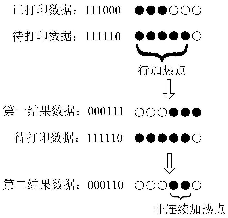
[0041] During printing, the print data is specifically divided into multiple lines of print data, and by reading the print data line by line, heating printing of each line is completed in turn. Specifically, in each line of print data, e...
Embodiment 2
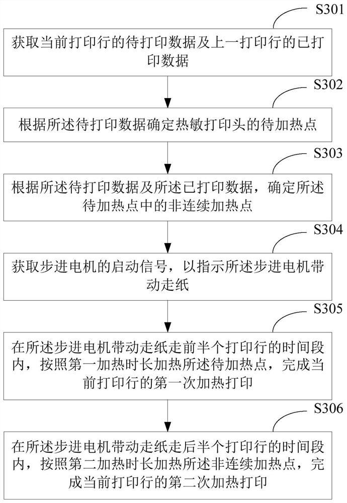
[0068] image 3 It shows a schematic flow chart of the second thermal printing method provided by the embodiment of the present application, and the details are as follows:
[0069] In S301, the data to be printed of the current printing line and the printed data of the previous printing line are acquired.
[0070] S301 in this embodiment is the same as S101 in Embodiment 1. For details, please refer to the relevant description of S101 in Embodiment 1, and details are not repeated here.
[0071] In S302, a point to be heated of the thermal print head is determined according to the data to be printed.
[0072] S302 in this embodiment is the same as S102 in Embodiment 1. For details, please refer to the relevant description of S102 in Embodiment 1, which will not be repeated here.
[0073] In S303, according to the data to be printed and the data already printed, non-continuous heating points among the points to be heated are determined.
[0074] S303 in this embodiment is th...
Embodiment 3
[0083] Figure 5 A schematic flowchart of the third thermal printing method provided by the embodiment of the present application is shown, and the details are as follows:
[0084] In S501, the to-be-printed data of the current printing line and the printed data of the previous printing line are acquired.
[0085] S501 in this embodiment is the same as S101 in Embodiment 1. For details, please refer to the relevant description of S101 in Embodiment 1, which is not repeated here.
[0086] In S502, the to-be-heated point of the thermal print head is determined according to the to-be-printed data.
[0087] S502 in this embodiment is the same as S102 in Embodiment 1. For details, please refer to the relevant description of S102 in Embodiment 1, which is not repeated here.
[0088] In S503, according to the to-be-printed data and the already-printed data, a discontinuous heating spot among the to-be-heated spots is determined.
[0089] S503 in this embodiment is the same as S103...
PUM
 Abstract
Description
Claims
Application Information
 - R&D
- Intellectual Property
- Life Sciences
- Materials
- Tech Scout
- Unparalleled Data Quality
- Higher Quality Content
- 60% Fewer Hallucinations
Browse by: Latest US Patents, China's latest patents, Technical Efficacy Thesaurus, Application Domain, Technology Topic, Popular Technical Reports.
© 2025 PatSnap. All rights reserved.Legal|Privacy policy|Modern Slavery Act Transparency Statement|Sitemap|About US| Contact US: help@patsnap.com


