Unlocking device
A technology for unlocking devices and unlocking sleeves, which is applied in the direction of power devices, electric power devices, transportation and packaging, etc. It can solve the problems of long time spent, long charging time, damage to locking device components, etc., and achieves simple and labor-saving operations and reduces Hard damage, the effect of improving the service life
- Summary
- Abstract
- Description
- Claims
- Application Information
AI Technical Summary
Problems solved by technology
Method used
Image
Examples
Embodiment 1
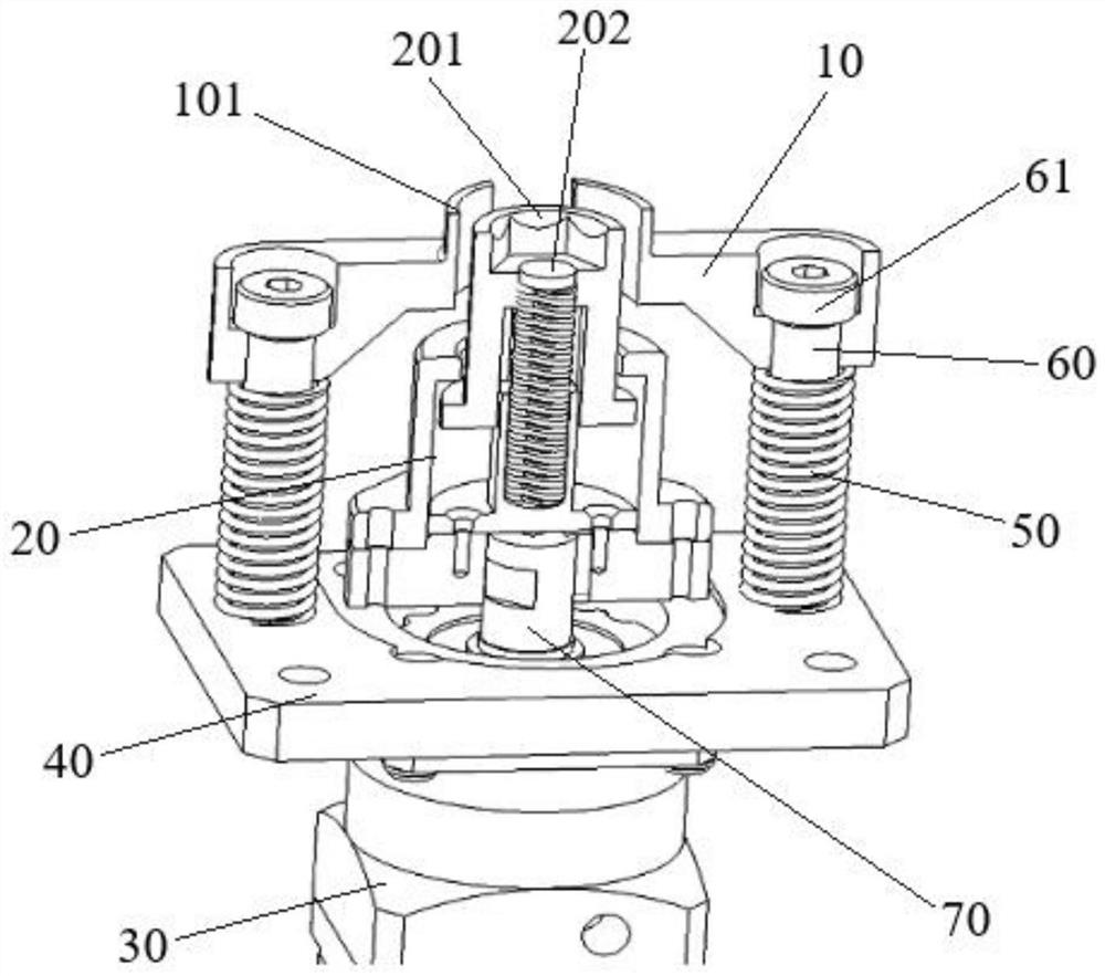
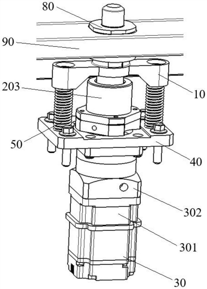
[0031] combine Figure 1 to Figure 5 , this embodiment provides an unlocking device for unlocking and unlocking the battery pack locking device 80 of an electric vehicle, such as image 3 , Figure 4 as well as Figure 5 As shown, the locking device 80 generally includes a screw, one end of which is a lock head 801, and in order to take into account the convenience of battery pack replacement and the firmness of installation, the locking device 80 is also provided with an anti-unlocking device, which includes a sleeve On the screw rod and the anti-retraction ring 802 that can move axially relative to the screw rod, the end of the screw rod close to the lock head 801 is provided with a flange surface 803, and the flange surface 803 and the anti-retraction ring 802 are provided with teeth that cooperate with each other. The anti-unlocking structure realizes the anti-unlocking function through the mutual meshing of the tooth-shaped structures; retaining ring 802 .
[0032] An...
Embodiment 2
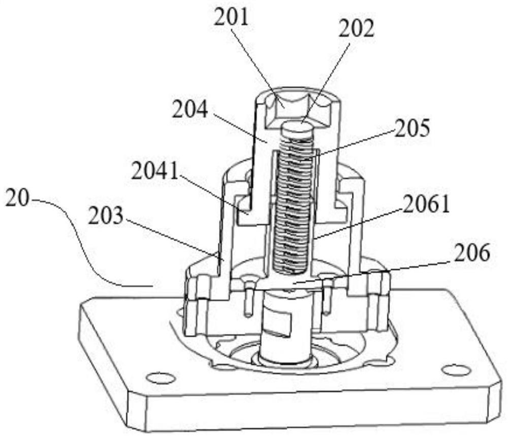
[0043] combine Figure 1 to Figure 5 , this embodiment provides an unlocking device, the screw mechanism 20 also includes a screw housing 203, an unlocking sleeve 204, a second spring 205 and a second spring support seat 206, the screw housing 203 is arranged on the On the mounting plate 40, the second spring 205 is arranged between the unlocking sleeve 204 and the second spring support seat 206, and the second spring support seat 206 is connected to the motor 30 through the transmission shaft 70 The socket part 201 is located at the end of the unlocking sleeve 203, and the unlocking sleeve 204 can move relative to the second spring support seat 206 under the action of the second spring 205; preferably, The second spring 205 has automatic neutrality, and can pull the movement of the unlocking sleeve 204 along the central axis where it is located; the mounting plate 40 is provided with an opening for the transmission shaft 70 to pass through; The screw mechanism 203 is located...
Embodiment 3
[0047] combine Figures 1 to 5 , this embodiment provides an unlocking device, the second spring support seat 206 is also connected with a guide part 2061, one end of the second spring 205 is connected with the guide part 2061; the guide part 2061 can The relative axial movement of the unlocking sleeve 204 described above serves to further guide the direction.
[0048] More preferably, the guide portion 2061 is provided with a groove, and one end of the second spring 206 is disposed in the groove.
[0049] The unlocking sleeve 204 is provided with a cavity, the other end of the second spring 205 is disposed in the cavity, the inner diameter of the cavity is larger than the outer diameter of the guide part 2061, and the guide part 2061 is at least partly set in the cavity of the unlocking sleeve 204 .
[0050] The unlocking sleeve 204 and the guide part 2061 are provided with connecting keys that cooperate with each other, and the connecting keys are arranged along the vertic...
PUM
 Abstract
Description
Claims
Application Information
 - R&D
- Intellectual Property
- Life Sciences
- Materials
- Tech Scout
- Unparalleled Data Quality
- Higher Quality Content
- 60% Fewer Hallucinations
Browse by: Latest US Patents, China's latest patents, Technical Efficacy Thesaurus, Application Domain, Technology Topic, Popular Technical Reports.
© 2025 PatSnap. All rights reserved.Legal|Privacy policy|Modern Slavery Act Transparency Statement|Sitemap|About US| Contact US: help@patsnap.com


