
Forced oil circulation transformer oil-submerged pump fault monitoring device and monitoring method

A forced oil circulation and fault monitoring technology, which is applied in the field of forced oil circulation transformer submersible pump fault monitoring device, can solve the problems of continuous fault development, complex judgment process, slow judgment speed, etc., achieve good social and economic benefits, and reduce judgment time The effect of high length and monitoring accuracy

Active Publication Date: 2020-12-11
CENT CHINA BRANCH OF CHINA DATANG CORP SCI & TECH RES INST CO LTD
View PDF5 Cites 6 Cited by
  • Summary
  • Abstract
  • Description
  • Claims
  • Application Information

AI Technical Summary

Problems solved by technology

During the daily abnormal analysis of the chromatographic data of the main transformer, it will be checked whether the fault is caused by the failure of the submersible pump. This process usually lasts for several weeks or months, and the operating conditions of the transformer will not be completely consistent during the judgment process, which will be affected by variables such as load, ambient temperature, and the number of pumps started (affecting the oil circulation speed) , the judgment process is relatively complicated and the judgment speed is slow
If the fault is not caused by the failure of the submersible pump, but the internal fault of the main transformer body, too long judgment time will cause the fault to continue to develop, resulting in the failure of the main transformer body

Method used


Image

  • Forced oil circulation transformer oil-submerged pump fault monitoring device and monitoring method
  • Forced oil circulation transformer oil-submerged pump fault monitoring device and monitoring method
  • Forced oil circulation transformer oil-submerged pump fault monitoring device and monitoring method

Examples


Embodiment Construction

[0019] The specific implementation manners of the present invention will be described in further detail below in conjunction with the accompanying drawings.

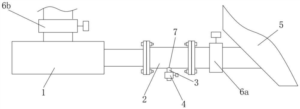
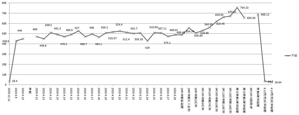
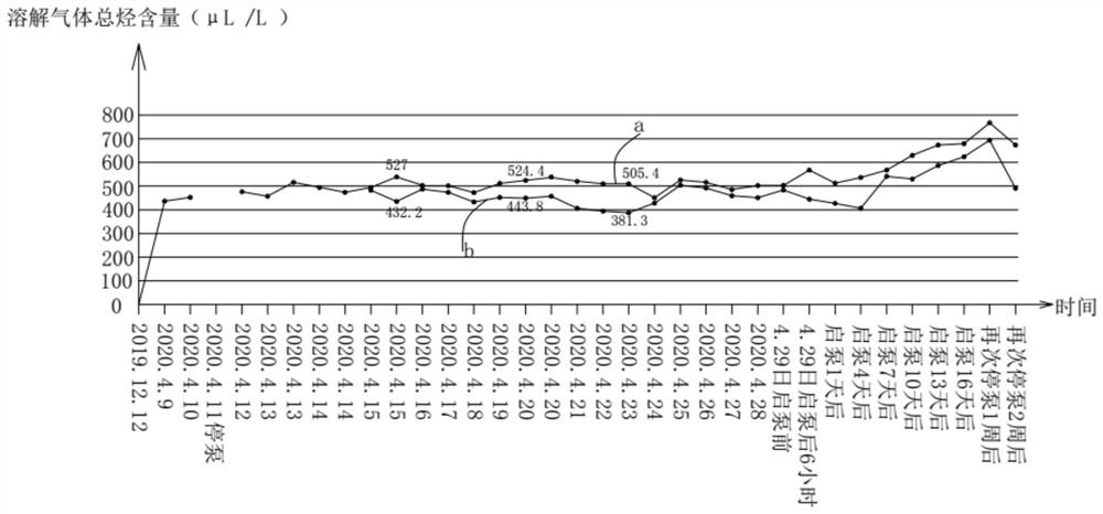
[0020] Depend on Figure 1-3 Given, a kind of forced oil circulation transformer submersible pump failure monitoring device of the present invention comprises main transformer 5 and submersible pump 1, and the oil outlet of submersible pump is connected with the oil inlet of main transformer 5 through oil pipeline 2, and described oil pipeline 2 is provided with a sampling port 7 for collecting oil samples, a submersible pump outlet valve 6a is provided on the pipeline between the sampling port and the main transformer 5, and a submersible pump inlet valve 6b is provided on the pipeline connected to the inlet of the submersible pump 1. The monitoring device also includes a transformer oil chromatography tester for detecting the total hydrocarbon content of dissolved gas in the oil sample taken from the sampling port.

...


PUM


Abstract

The invention relates to a forced oil circulation transformer oil-submerged pump fault monitoring device and monitoring method. According to the technical scheme, an oil outlet of an oil-submerged pump is connected with an oil inlet of a main transformer through an oil conveying pipeline, the oil conveying pipeline is provided with a sampling port for collecting an oil sample, an oil-submerged pump outlet valve is arranged on a pipeline between the sampling port and the main transformer, and an oil-submerged pump inlet valve is arranged on a pipeline connected with an inlet of the oil-submerged pump; and the online monitoring device further comprises a transformer oil chromatography tester used for detecting the total hydrocarbon content of dissolved gas in an oil sample taken out from thesampling port. The device can realize online measurement of the oil sample at the sampling port of the oil-submerged pump in an operation state for analysis of dissolved gas in oil, intuitively and effectively judges whether the oil-submerged pump is in a fault state or not through data, is high in monitoring accuracy, provides reliable reference data for equipment operation, and greatly shortensthe fault judgment time length of the oil-submerged pump of a forced oil circulation transformer.

Description

technical field [0001] The invention relates to a fault monitoring device and a monitoring method for a forced oil circulation transformer submersible pump. Background technique [0002] At present, the main transformers of power plants and the large-capacity main transformers of substations ensure that the transformer cooling system can play the best role. Usually, a submersible pump is installed between the main transformer body of the radiator. The submersible pump speeds up the oil flow, thereby improving the cooling efficiency. The submersible pump is installed between the main transformer (main transformer) body and the radiator. The oil of the submersible pump, the radiator oil and the oil of the main transformer body are connected. The motor of the submersible pump is connected to the three-phase power supply, and the motor rotor drives the oil flow to The radiator oil is pumped into the main transformer body through the submersible oil pump. When the submersible pu...

Claims


Application Information

Patent Timeline
IPC IPC(8): F04B51/00G01N30/02G01N30/20G01N33/28
CPCF04B51/00G01N30/02G01N30/20G01N33/2841
Inventor 王立楠马云飞张晓鹏韩金华郑豫生樊东方郭晓锋靳鹏超黄卫华都扬赵伟程孙彬张昕
Owner CENT CHINA BRANCH OF CHINA DATANG CORP SCI & TECH RES INST CO LTD
Learn More